The rigging system – Grip Factory Munich GF-9 User Manual
Page 10
GF-9 Crane System Instruction Manual
Page: 9
The rigging system
To enhance the rigidity and reduce the strain to the GF-9 arm, a rigging system consisting
of various rods and a V shaped harness is required. The rigging system must be used for
all versions.
To simplify assembly, all rigging rods, with the exception of the ones required for the
100cm and 50cm sections, are identical.
The length of the rigging depends on the number of extensions to be used. As a rule, the
rigging runs from the rigging harness mounted on the pivot section to the last section
(Versions 1 to 5) at the front or end of the crane. From Version 6 onwards the rigging runs
from the rigging harness mounted on the pivot section to the last section 150cm / 5ft
section at the front or end of the crane. Detailed drawings can be found in the following
pages. A double rigging system is required as of version 9. In this case the lower rigging
rods connect from the rigging harness to the second section whereby the 2 rods with the
double connectors should be connected to the second extension.
General instructions for assembling the rigging:
1.
After connecting the turnbuckles to the rigging harness, connect the required rigging
rod and secure the rods with the provided safety pin.
2.
Depending on the version, attach the required number of rods and secure them with
the provided safety pins.
3.
Version 9 onwards requires a double rigging system (upper/long and lower/short).
The lower rods connect to the second extension. The 2 rods with the double
connectors as shown below must be connected to the second section with the vertical
connector in an upward direction ( accepts the adjustable rigging rod support).
Versions 1 to 8 have a single rigging system.
4.
When the rods are connected together and secured with the respective safety pins,
connect the front rods to the connections for rigging rods on the respective section.
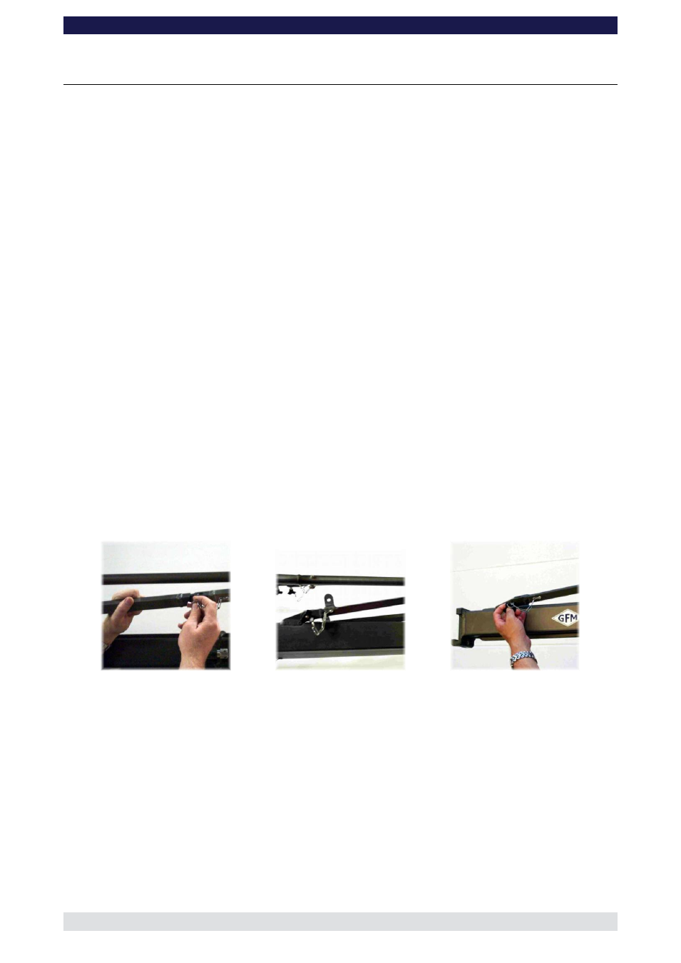
Connecting the rigging rods
Rigging rod with double connectors
Connection for rigging rod
Attention: for certain versions it is necessary to use a rigging rod connector between
the second and third rigging rod (as seen from the pivot section) in the upper (long)
rigging.
5.
When all the required rods are in place and connected, the turnbuckles on the rigging
harness can be hand turned until the rods are taut . The turnbuckles should adjust the
run of both sets of rods equally so that the arm is not bent or pulled to one side. Over
adjusting of the rods should be avoided.