Greenheck Waterwash (458292) User Manual
Page 20
20
April 2005
®
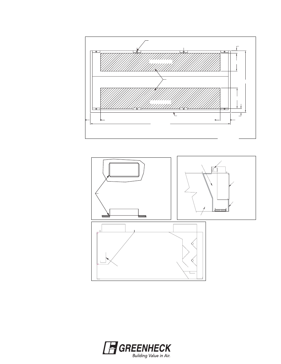
DUCT COLLAR INSTALLATION INSTRUCTIONS
FOR GH, GW, GK, GX, & GG SERIES HOODS
8.00
Hood Length
Front of Hood
Supply Plenum
Duct Cut Out Area
Exhaust Plenum
Hangar Bracket
3.00
10.00
Hood Width
16.00
3.00
8.00
1.
The exhaust duct
connection needs to be
located within 48 in. from
the center of the hood
length to the center of
the duct connection.
(see Fig. 20A)
2.
The exhaust duct
connection is to be a
continuous liquid tight
weld. Weld with a non-
ferrous filler wire, such
as silicon bronze or
stainless steel filler
wire. Protect all
stainless steel areas
from weld splatter.
3.
The supply duct
connection is tack
welded at 1 in. to 2 in.
intervals, or sheet metal
screws at 3 in. to 6 in.
spacing to the hood.
(see Fig. 20B)
4.
The deflector is centered
under the supply duct
collar. (see Fig. 20C)
5.
For hoods that are
insulated, the edges of
the insulation need to be
taped after the hole is
cut, (the insulation tape
is to be provided by
others).
6.
On combination hoods,
make sure the fire
damper is located over
the internal supply
chamber. (see Fig. 20D)
Return to page 9.
Fig. 20A
Top View of the Hood
1" TO 2" TACKS OR SHEET METAL SCREWS AT 3" TO
6" SPACING TO HOOD.
SUPPLY DUCT CONNECTION TO BE TACK WELDED WITH
CONNECTION
SUPPLY DUCT
Fig. 20B
Fig. 20D
Fig. 20C
SUPPLY
FIRE DAMPER
INTERNAL
SUPPLY
CHAMBER
HOOD
INSULATED
SUPPLY PLENUM
EXHAUST
CAPTURE
DEFLECTOR TO BE PLACED CENTERED
UNDER THE SUPPLY DUCT COLLAR
Note: UL listed hood
assembly to be used
only with Greenheck
Fan Corp. labeled
subassembly for
exhaust hood without
exhaust damper part
Number DC.