Vgn technology control flow chart - single fan, General electrical controls information – Greenheck Vektor Laboratory Exhaust with VGN Technology Electrical Controls Information (476072) User Manual
Page 5
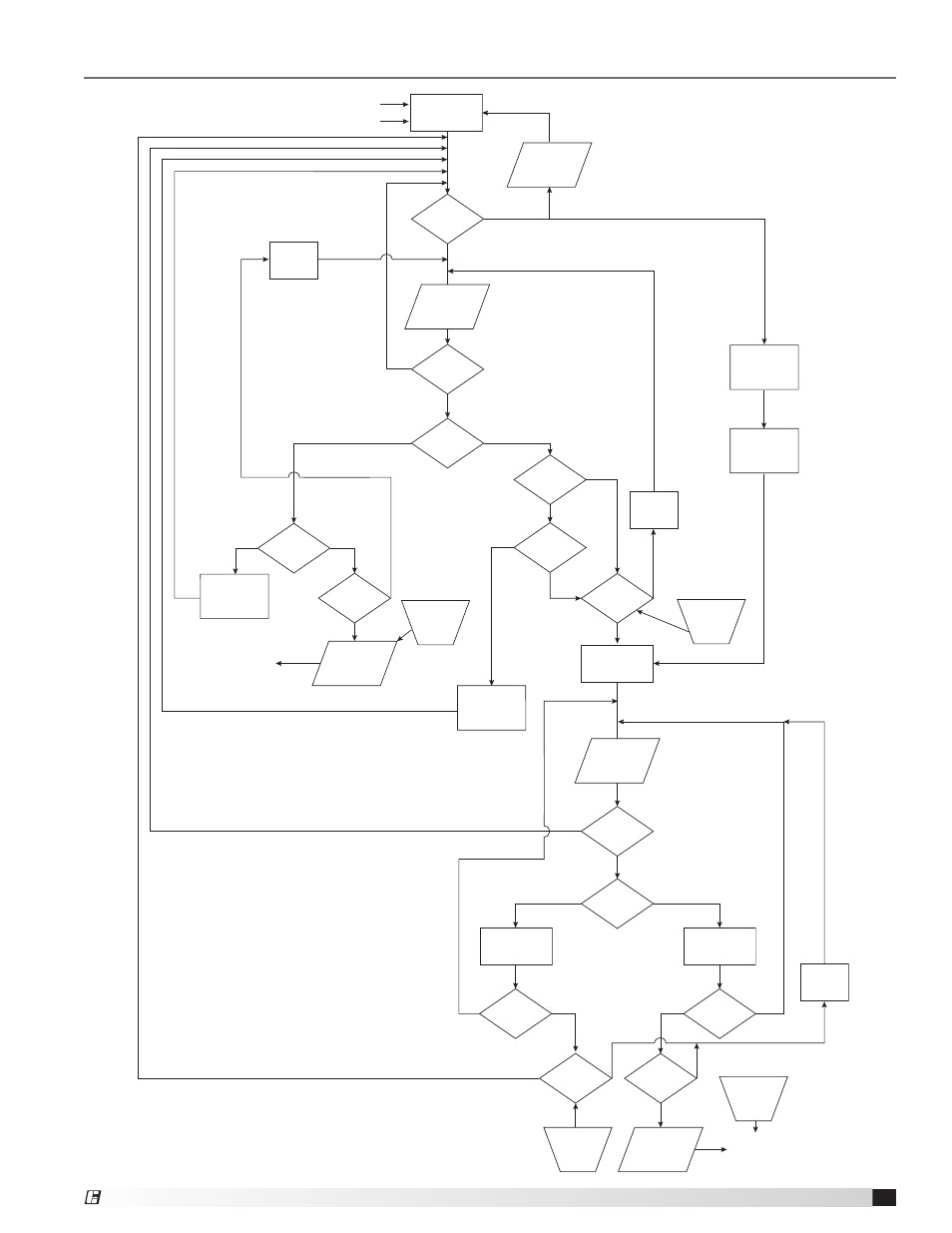
General Electrical Controls Information
VGN Technology Control Flow Chart - Single Fan
Positive Pressure Fault
Negative Pressure Fault
Above Setpoint
(more positive)
Send to BMS
Controller
Send to BMS
Controller
Below Setpoint
(more negative)
Above Setpoint
(more positive)
Below Setpoint
(more negative)
Yes
Yes
No
No
No
No
No
No
No
No
No
No
No
Yes
Yes
Yes
Yes
No
Yes
Yes
Yes
Yes
Yes
Yes
Yes
Yes
BMS Control
Drive Fault
Alarm
Drive
Fault Bypass
Mode
Static
Pressure =
Setpoint
Fan at
Full Speed
Required
Nozzle Area
Static
Pressure
Value
Static
Pressure
Valve
VFD
at Full
Speed
Increase
Fan Speed
Positive
Pressure
Alarm
Negative
Pressure
Alarm
Time Period
Met?
Max. VFD
Monitor
Time
Min. VFD
Monitor
Time
Damper
Position
Monitor
Time
Time Period
Met?
Time Period
Met?
Time Period
Met?
BMS Control
Bypass Damper
PID
Decrease
Fan Speed
Static
Pressure
Value
Open
Bypass
Damper
Close
Bypass
Damper
Bypass
Feedback
= Maximum
VDC
Bypass
Feedback
= Mimimum
VDC
Reset by
BMS
Reset by
BMS
Reset at
Fault CLR
Reset at
Fault CLR
Nozzle
Feedback at
Minimum
VFD at
Minimum
Speed
Static
Pressure =
Setpoint
Static
Pressure
Value
5
VGN Technology
®
- VCD-40 Extension Pin Kit 316SS (475290) (2 pages)
- 331-2856, 332-2856 - Siemens 6 Actuator (454206) (2 pages)
- 331-2976, 332-2976 - Siemens 4 Actuator (454202) (2 pages)
- 331-4551, 332-4551 - Siemens 3 Actuator (454201) (2 pages)
- Adjustable Pressure Controller (468292) (3 pages)
- 7800 Series Relay Modules (12 pages)
- Standard Control - MSSC (476372) (4 pages)
- NFB Series Actuators External Mount (464236 IOM) (2 pages)
- GND Series External Mount (473723) (4 pages)
- Amplifier for 7800 Series Relay Module (8 pages)
- APEX Curbs (462831) (4 pages)
- AMD-xx-TD Transmitter (35 pages)
- Blade Seal Repalcement (HCDR Series) (1 page)
- VCD (463384) (12 pages)
- BAPI Zone Pressure Touch (ZPT) Sensor (6 pages)
- VCD (463384) (10 pages)
- Blade Seal Replacement (HCD Series) (2 pages)
- BR Series - Counterweight Adjustment (469420) (4 pages)
- Leakage Rated Ceiling Radiation Dampers (475063 IOM). (32 pages)
- Canopy Hoods (452413 IOM) (36 pages)
- Clean-Out Port Kit (472428) (1 page)
- Centrifugal (CSW, BIDW, AFDW), Industrial (IPA, IPO, IPW) and Filtered Supply (LSF) (463687) (12 pages)
- Close Indicator Switch for Fire Dampers (474050) (1 page)
- Concrete Floor with Steel Deck Supplement (463562) (1 page)
- CRD-3XX and CRD-7XX Series for SP fans (452832) (2 pages)
- VCD (463384) (8 pages)
- VCD (463384) (4 pages)
- Single Side Retaining Angle (52 pages)
- DG / DGX with Pilot Ignition (463555 IOM) (Pre-2008) (48 pages)
- DG / DGX with Direct Spark (470652) (40 pages)
- Digital Temperature Interlock (474750 IOM) (Pre November 2012) (8 pages)
- DGK (468695) (20 pages)
- DG / DGX with Pilot Ignition (463555 IOM) (Pre-2008) (52 pages)
- Double Gland Axle Seal Replacement (1 page)
- Dock Arm Kit (475367) (4 pages)
- Duct Heaters Series IDHB and IDHC (478052) (8 pages)
- EHH-601D, Channel Installation (474643) (10 pages)
- EHH-601D, Channel Installation with VCD-40 Damper (474644) (8 pages)
- EHH-601D, Flange/Sleeve Installation (474641) (8 pages)
- GM Series (468391) (4 pages)
- EHH-601D, Flange/Sleeve Installation with VCD-40 Damper (474642) (8 pages)
- El-O-Matic E and P Series (12 pages)
- Energy Recovery Filter Hood System (8 pages)
- ERV-582/120 Curbs (460988) (4 pages)
- ESD-635D, Chanel Installation (474639) (10 pages)