Controller menu screens – Greenheck Vektor Laboratory Exhaust with VGN Technology Electrical Controls Information (476072) User Manual
Page 21
Controller Menu Screens
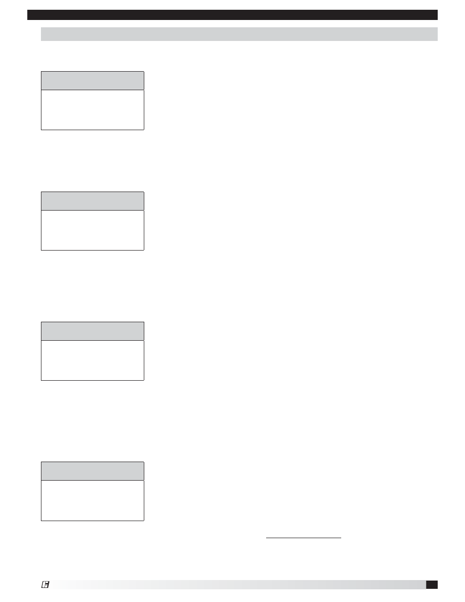
The following value ranges are specific to the Air Flow menu screen.
Flow Active reading calculated by the Sure-Aire system.
English = CFM; Metric = m
3
/hr
Flow VDC Scaled voltage output specific to the flow scale.
0 VDC = no flow; 10 VDC = maximum flow
Flow Scale Flow range specific to VGN fan.
English = CFM; Metric = m
3
/hr.
Nozzle Open Active reading stating the % open of the VGN nozzle.
0% = nozzle closed; 100% = nozzle open
The values in this menu are not user-editable and are locked by the controller program.
GREENHECK VGN
AIR
FLOW
FLOW
xxxxx
FLOW VDC X.X VDC
LOW SCALE 0 TO XXXXX
NOZZLE
OPEN
XXX
%
The nozzle controller consists of five menu screens to operate the VGN system. The following information describes
the menu screens in detail.
GREENHECK VGN
SYSTEM
STATUS
FAN
STATUS
XXX
VELOCITY
XXX
FAN
FLOW
XXX
ALARM CONTACT XXX
The following value ranges are specific to the System Status menu screen.
Fan Status Shows the status of the fan.
On or Off
Velocity Determines if outlet velocity is acceptable per system setting.
OK or Low
Fan Flow Determines if fan flow is acceptable per required nozzle area and velocity.
OK or Low
Alarm Contact Alarm and contact closure for the following.
Alarm list:
a. Velocity is below the required preset system value.
b. Fan is shown as running but no flow is being created.
The values in this menu are not user-editable and are locked by the controller program.
GREENHECK VGN
SYSTEM
SETTINGS
H FAN SIZE XX
FLOW
MEASURE
XXXXX
UNITS
XXXXXX
ELEVATION
XXXXX
OUTLET VELOCITY XXXX
The following value ranges are specific to the System Settings menu screen.
H / M / C Fan Size Factory set for system fan size. Selects the correct fan
variables for the control.
Flow Measure Sets the location of the airflow monitor location.
Inlet or outlet condition
Units Sets up the control screen variables for the system.
English or Metric
Elevation Location above sea level the system is located to set air density.
0 to 10,000 feet
Outlet Velocity Required velocity at the VGN Nozzle outlet.
3,000 to 4,000 FPM; 912 to 1216 MPM.
All the values in this menu can be changed by the user. Note factory settings prior to making
adjustments.
GREENHECK VGN
TEST AND BALANCE
T&B
BALANCING
XXX
NOZZLE
%
OPEN XXX
FLOW
CORRECT
XXXX
The following value ranges are specific to the Test and Balance menu screen.
T&B Balancing Used to start the balancing process of the system.
Yes or No.
Nozzle % Open Gives Test and Balance personnel complete control of nozzle
regardless of fan flow.
0% = closed; 100% = open
Flow Correct “K” factor for Test and Balance personnel to measure and adjust
airflow. Note that “K” value is not CFM, but subtracts or adds to
the flow calculation within the program.
-2000 to +2000
All the values in this menu can be changed by the user. Note factory settings prior to making
adjustments.
Electrical Controls Information for Customer-Supplied Variable Frequency Drive
21
VGN Technology
®