Wiring installation, System components – Greenheck Vektor Laboratory Exhaust with VGN Technology Electrical Controls Information (476072) User Manual
Page 3
General Electrical Controls Information
Wiring Installation
The following items are a list of requirements necessary
to install the controls for the VGN Technology system.
1. Mount variable frequency drive in the desired
location; indoors or outdoors. Maximum distance
from fan is 100 feet (30.5 meters).
2. Mount transducer/terminal enclosure at fan or
bypass air plenum (BAP).
3. Run main power wiring from building breaker panel
to variable frequency drive. By others.
4. Run motor power wiring from service disconnect
switch to variable frequency drive. Wire length to be
less than 100 feet. By others.
5. Connect control wiring pigtail (by factory) from VGN
nozzle actuator(s) to transducer/terminal enclosure.
(See wiring diagram).
Optional: Connect wiring from isolation damper
actuator(s) to transducer/terminal enclosure. By
others.
6. Run control wiring from transducer/terminal
enclosure to variable frequency drive or nozzle
controller terminal strip. Wire length to be less than
100 feet (See wiring diagram).
7a. Run communication cable from variable frequency
drive to Building Management System (BMS). See
VFD manual for type and maximum length. By
others. (VGN with factory-supplied VFD).
7b. Run VGN nozzle controller system wiring from main
control panel to Building Management System
(BMS). By others. (Customer-supplied VFD).
8. Run nozzle actuator feedback control wire from
transducer/terminal enclosure at the fan to BMS
controls.
9. Install 1/4 inch pressure tubing (by others) from
transducer/terminal enclosure to Sure-Aire
connection plate on fan. By others.
10. Install BMS with duct pressure control system. By
others.
11. For specific device installation reference the
appropriate component cut sheet or IOM. Also
reference the following system and wiring diagrams
on pages 4 and 7 for more detail.
NOTE
All field installation and wiring of electrical
equipment must be done to meet NEC and local
codes.
NOTE
Be sure to use appropriately sized wire for the full
load amp draw.
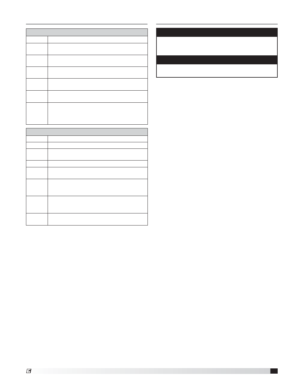
System Components
System Components (supplied by Greenheck)
Quantity
Description
1
Pressure transducer with adjustable pressure
range and VDC signal
1
VFD with bypass mode and integrated controller
(VGN with factory-supplied VFD)
1
VGN nozzle controller.
(VGN, customer-supplied VFD)
1 to 4
Actuator motor(s) (nozzle)
24 volts, modulating VDC signal with feedback
Varies
Actuator motor (bypass damper), if provided by
manufacturer
Varies
Actuator motor (isolation damper) 24 volts,
open/close. Quantity will be zero if isolation
damper actuator is supplied by others or if gravity
style isolation damper is used.
System Components (customer-supplied)
Quantity
Description
Varies
Wiring, conduit, miscellaneous fittings
1
Building control system with required
communication wiring and shielding
Varies
Pressure transducer for duct pressure
Varies
Actuator motor (bypass damper) if provided by
others
1
Actuator motor (isolation damper), if provided
by others. Quantity will be zero if gravity style
isolation damper is used.
Varies
1/4 inch tubing. Connection from Sure-Aire
termination plate mounted on fan to mounting
location of transducer/terminal enclosure.
1
Fan motor VFD.
(VGN, customer-supplied VFD)
3
VGN Technology
®