Pressure transducer auto zero, Inputs/outputs, Led status – Greenheck Vari-Green Control - Constant Pressure/Air Flow Control (479653) User Manual
Page 4: Run/prog mode, Run mode
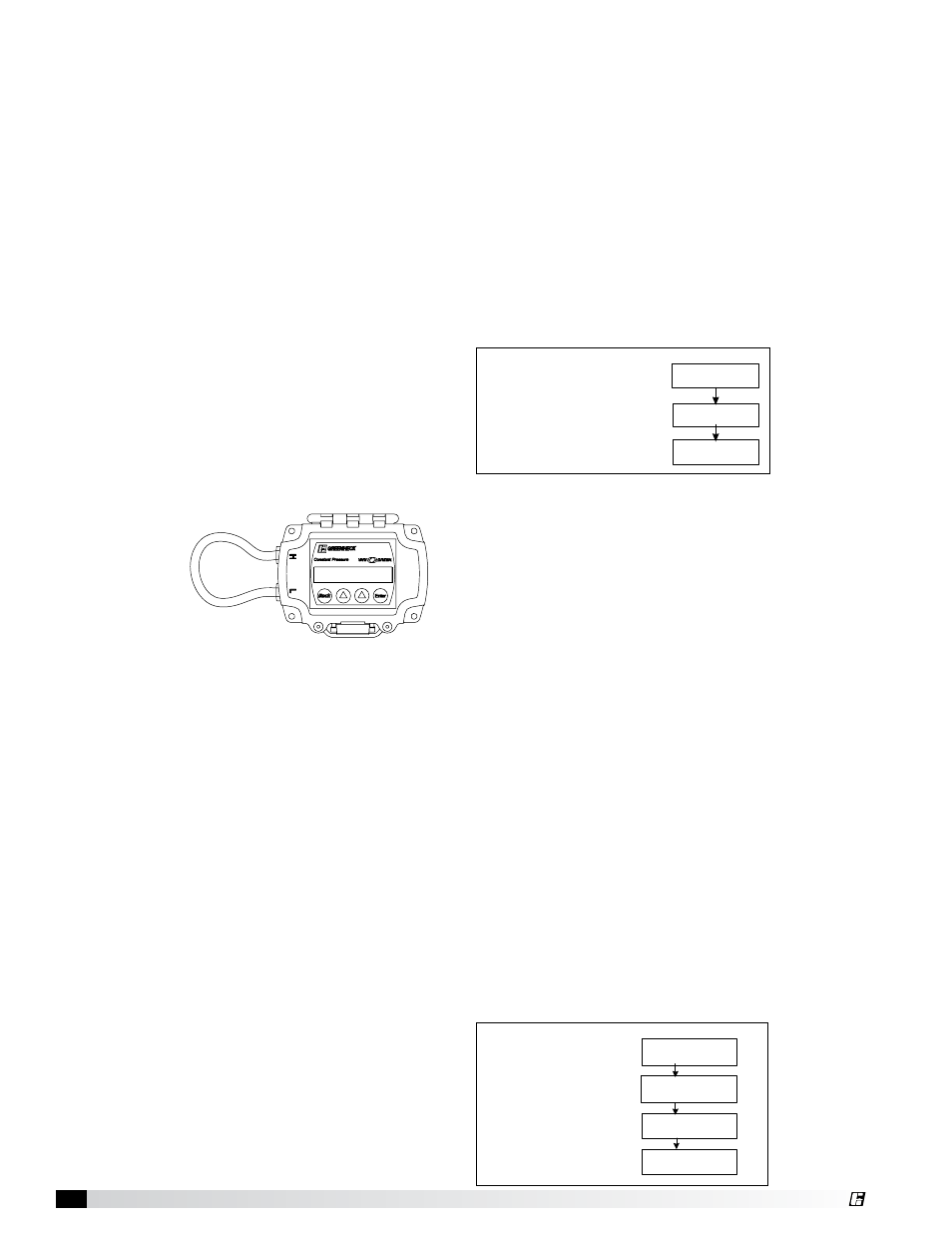
Pressure Transducer Auto Zero
The integral and remote pressure transducer includes
an auto zero function. There is an auto zero button on
the inside of the enclosure. If the controller is already
installed, remove field tubing and connect the “H” and
“L” port of the pressure transducer together with a
short piece of tubing (Fig. 3). Press the auto zero
button inside the
enclosure. When
the LED stops
flashing, remove
the tubing and
reconnect the
existing field
tubing.
Inputs/Outputs
The controller contains the following inputs/outputs:
Inputs:
Remote Override (digital, dry contact)
• Activating this input will force the Fan Speed
output to a fixed % (adjustable)
Remote Setpoint (analog, 0-10V or 2-10V)
• A voltage signal can be sent to the control to
remotely adjust the setpoint.
Remote Transducer (analog, 0-10V)
• Not available on controller with integral
transducer.
Outputs:
Fan Speed (analog, 0-10V, 2-10V)
Pressure/Airflow Reference (analog, 0-10V)
• The output will send the actual pressure/airflow
value to another device, such as BMS.
Relay (digital, 0.5A rating)
• The relay output will close when the Fan Speed
output is above a set % (adjustable). Common
uses are to signal a dirty filter in airflow mode or
signal another device that the fan is being called
to run.
FIG. 3
Pressure tubing connected for auto zero
LED Status
A status LED exists on the control and remote pressure
transducer.
Control:
Green = Normal Operation
Pink = Programming/manual mode
Flashing Yellow = Cutout timer is active
Solid Yellow = Cutout mode is active
Red = Override active
Transducer:
Red = >1.00 in.WC (>249Pa)
Green = 0 —1.00 in.WC (0-249Pa)
Yellow = 0 in.WC (0Pa)
Blue = 0 — -1.0 in.WC (249Pa)
Pink = < -1.00 in.WC (249Pa)
RUN/PROG Mode
Run and Program mode are set using the selector
switch on the inside of the control. Open the control
enclosure to access the switch.
RUN Mode
This control has two major functions – constant
pressure mode and constant airflow mode.
(Set using initial set up menu. pg. 6 & 7)
Constant Pressure Mode - the control will
automatically adjust the speed of the fan to maintain a
constant static pressure in a duct or room.
The display will show the following variables
(touch the arrow buttons to change the display):
Cutout – The following definitions will be used to
provide clarity in the explanation of the cutout feature.
Primary Fan:
The controller is connect to this fan.
Secondary Fan:
Any fan, other than the primary fan, that
influences the pressure in the system
The cutout feature is available to turn the primary fan off
in times of no demand from the secondary fans.
There are three parameters related to the cutout
function: Cutout %, Cutout Delay Time and Return from
Cutout Pressure Setpoint.
Cutout mode is activated when the fan speed
output % is less than the cutout % setpoint. After the
Cutout Delay Time has elapsed, the control will turn the
output OFF.
A change in system pressure is needed to turn the
output back ON. This value is adjustable to prevent false
pressure fluctuations from turning the fan back on.
Constant Airflow Mode – the control will automatically
adjust the speed of a fan to maintain a constant airflow
rate in a duct.
The display will show the following variables(touch the
arrow buttons to change the display):
Static Pressure Reading
Output %
Pressure Setpoint
Cutout Threshold %
Output: XX.X%
Ps: -X.XX in WC
Set: -0.10 in WC
Ps: -X.XX in WC
Cutout: 20.0%
Ps: -X.XX in WC
Output: XX.X%
Flow: XXXXX CFM
Dp: X.XX in WC
Flow: XXXXXX CFM
Set: XXXXX CFM
Flow: XXXXX CFM
If control mode=
Constant
Pressure
If control mode=
Constant Airflow
Vel: XXXXX FPM
Flow: XXXXXX CFM
Airflow Reading
Output %
Differential Pressure
Reading
Velocity Reading
Airflow Setpoint
Output: XX.X%
Ps: -X.XX in WC
Set: -0.10 in WC
Ps: -X.XX in WC
Cutout: 20.0%
Ps: -X.XX in WC
Output: XX.X%
Flow: XXXXX CFM
Dp: X.XX in WC
Flow: XXXXXX CFM
Set: XXXXX CFM
Flow: XXXXX CFM
If control mode=
Constant
Pressure
If control mode=
Constant Airflow
Vel: XXXXX FPM
Flow: XXXXXX CFM
Constant Pressure Control
4