General operation, Display, Touch buttons – Greenheck Vari-Green Control - Constant Pressure/Air Flow Control (479653) User Manual
Page 3
you intend to control the static
pressure. It should be located
a minimum of 10’ away from
the inlet/outlet of the fan/
damper to ensure stable
operation.
The duct static probe is always
connected to the “H” port
of the control/transducer.
The “L” port is the reference
port and can remain open to
atmosphere or plumbed to another location.
Room Static Probe
The room static probe is used to sample the pressure in
an open space such as a room or hallway. The pressure
controlled room must be connected to the “H” port. The
“L” port is the reference port and can remain open to
atmosphere or plumbed to another location.
Alternatively, if the controller/transducer is mounted
in the space in which the pressure is to be controlled,
the “H” port can remain open and the “L” port must be
plumbed to another location for reference.
2-Piece Pitot Tube
The 2-piece pitot tube consists of a total pressure (P
T
)
probe and a static pressure (P
S
) probe. These probes
should be mounted in a straight section of ductwork
located away from elbows or transitions. The total
pressure probe can be identified by a 45deg. cut at the
end and the arrow identifying airflow direction on the
mounting flange.
Examples for mounting the probes are shown in FIG. 2
(A, B, C).
Connect the total pressure probe to the “H” port of the
control/transducer and the static pressure probe to the
“L” port.
AMS (Airflow Measuring Station)
The AMS should be mounted away from elbows and
transitions. Connect the “HIGH” port of the AMS to the
“H” port and the “LOW” port of the AMS to the “L” port
of the control/transducer.
FIG. 1
AIR FLOW
AIR FLOW
AIR FLOW
4-8 in.
2-4 in.
P
T
S
CORRECT
CORRECT
INCORRECT
12 in.
OR GREATER
P
T
P
T
P
S
P
S
P
(102-203mm)
(51-102mm)
(305mm)
FIG. 2
(A)
(C)
(B)
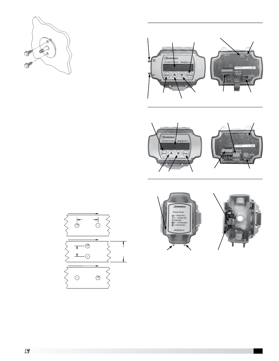
Display
The 2-line multi character display is backlit and is
used to read the status of the control as well as setting
parameters during programming.
Touch Buttons
The buttons on the front of the control are touch
sensitive, similar to the touch screen of a smartphone.
Gloves must be removed to ensure it senses your finger.
In RUN mode, the arrow buttons can be used to display
different process variables. In PROG mode, the arrow,
enter and back buttons are used to navigate the menus
and set parameters. When using the arrows to set
parameters, holding the button down will increase the
scrolling speed.
Remote Transducer
Pressure
Status LED
H Pressure Port
L Pressue Port
Wiring Connector
Auto Zero Button
Controller with Remote Transducer
Display
Back Button
Up Arrow
Down Arrow
Enter Button
Romote Transducer
Wiring Connector
Control Wiring
Connector
Power Wiring
Connector
PROG/RUN
Switch
Controller with Integral Transducer
H Pressure Port
Display
L Pressure Port
Back Button
Up Arrow
Down Arrow
Enter Button
PROG/RUN Switch
Control Wiring
Connector
Power Wiring
Connector
Auto Zero Button
General Operation
Constant Pressure Control
3