Specifications – Greenheck Vari-Green Control - Constant Pressure/Air Flow Control (479653) User Manual
Page 11
Assembly Part Numbers
Description
Assembly P/n Includes
Controller w/ Integral Transducer,
1 Duct Static Tap
872982
385604, 474748
Controller w/ Integral Transducer,
1 Room Static Tap
872983
385604, 474770
Controller w/ Integral Transducer,
2 Room Static Taps
872984
385604, 474770 (2)
Controller w/ Integral Transducer,
1 Duct Static and 1 Duct Total Tap
872985
385604, 474748,
475106
Controller, Remote Transducer,
1 Duct Static Tap
872986
385605, 385606,
474748
Controller, Remote Transducer,
1 Room Static Tap
872987
385605, 385606,
474770
Controller, Remote Transducer,
2 Room Static Taps
872988
385605, 385606,
474770 (2)
Controller, Remote Transducer,
1 Duct Static and 1 Duct Total Tap
872989
385605, 385606,
474748, 475106
Controller, Remote Transducer
872990
385605, 385606
Duct Air
Temp
Air Density Correction Factors
Elevation
Dimensions in feet and (meters)
°F (Deg. C)
0
500
1000
1500
2000
2500
3000
3500
4000
4500
5000
5500
6000
(0)
(152.4) (304.8) (457.2) (609.6) (762) (914.4) (1066.8) (1219.2) (1371.6) (1524) (1676.4) (1828.8)
-40 (-40)
0.79
0.81
0.82
0.84
0.85
0.87
0.88
0.9
0.92
0.93
0.95
0.97
0.99
-20 (-29)
0.83
0.85
0.86
0.88
0.89
0.91
0.93
0.94
0.96
0.98
0.99
1.02
1.04
0 (-18)
0.87
0.88
0.9
0.92
0.93
0.95
0.97
0.99
1
1.02
1.04
1.06
1.08
20 (-7)
0.91
0.92
0.94
0.96
0.97
0.99
1.01
1.03
1.05
1.07
1.08
1.11
1.13
40 (4)
0.94
0.96
0.98
1
1.01
1.03
1.05
1.07
1.09
1.11
1.13
1.16
1.18
70 (21)
1
1.02
1.04
1.06
1.08
1.1
1.12
1.14
1.16
1.18
1.2
1.22
1.25
80 (27)
1.02
1.04
1.06
1.08
1.1
1.12
1.14
1.16
1.18
1.2
1.22
1.25
1.27
100 (38)
1.06
1.08
1.1
1.12
1.14
1.16
1.18
1.2
1.22
1.25
1.27
1.29
1.32
120 (49)
1.09
1.11
1.13
1.16
1.18
1.2
1.22
1.24
1.27
1.29
1.31
1.34
1.37
140 (60)
1.13
1.15
1.17
1.2
1.22
1.24
1.26
1.29
1.31
1.34
1.36
1.39
1.41
160 (71)
1.17
1.19
1.21
1.24
1.26
1.28
1.31
1.33
1.35
1.38
1.4
1.43
1.46
180 (82)
1.21
1.23
1.25
1.28
1.3
1.32
1.35
1.37
1.4
1.42
1.45
1.48
1.51
200 (93)
1.25
1.27
1.29
1.32
1.34
1.36
1.39
1.42
1.44
1.47
1.49
1.53
1.55
Specifications
Input Power:
Current Usage:
12-32VDC, 18-28VAC
100 mA Max
Output:
LCD Display:
0-10VDC
(PID Output)
Pressure, CFM,
Output %
0-10VDC
(Pressure or Flow)
Control Modes:
N.O. Digital (configurable)
Pressure
(Direct and Rev. Acting)
Input:
Airflow (CFM) (M
3
/hr)
Override (Dry Contact)
Mounting:
Setpoint Range:
Four Ext. holes for
#10 Screws
-1.00" to +1.00" WC
(+/-249Pa)
Enclosure Material:
0-10,000 CFM
(16.990 m
3
/hr)
UV-Resistant Polycarbonate,
UL94V-0
Accuracy:
Enclosure Rating:
+/- 1.0% FS @ 80F
IP66, NEMA-4
Temperature
Compensation Range:
Environmental
Operating Range:
45 to 80ºF (7 to 26ºC)
-13 to 175ºF (-25 to 79ºC)
Port Connection:
0-95% RH
non-condensing
1/4 inch (6mm)Tubing
(1/8 to 3/16 inch ID)
(3 to 5mm ID)
Burst Pressure:
1.5psi (either port)
(10.342Pa)
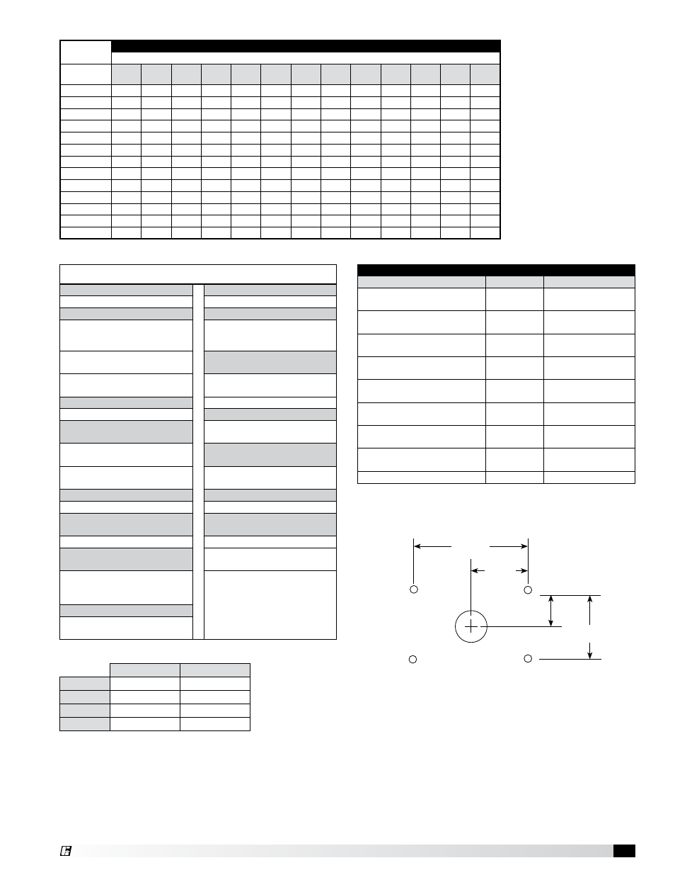
Note:
Four (4) #10 screws recommended with
5
⁄
32
in. (4mm)
pilot holes.
4
1
⁄
16
in.
(103mm)
2 in.
(51mm)
1-
7
⁄
16
in.
(37mm)
2-
7
⁄
8
in.
(53mm)
Mounting Hole Pattern
Ø
7
⁄
8
in.
(22mm)
Units:
Imperial
Metric
Length
In. / ft.
mm / m
Flow
CFM
m
3
/hr
Pressure
In. WC
Pa
Velocity
FPM
m/hr
Constant Pressure Control
11