Rail and roof curb mounting, Rail mounting and layout, Roof curb mounting – Greenheck MPX (472695) User Manual
Page 7: Install curb, Install ductwork, Set unit, Ductwork connections
Rail and Roof Curb Mounting
Rail Mounting and Layout
• The unit may be installed on rails provided and
installed by others. Ensure that rails are designed
to handle the weight of the unit and provide proper
load distribution on building supports.
• Make sure that rail positioning does not interfere
with the supply air discharge opening on the unit.
• Rails should run the width of the unit and extend
beyond the unit a minimum of 12 inches on each
side.
• Set unit on rails.
Roof Curb Mounting
Roof curb details, including duct location dimensions,
are available on the model’s roof curb assembly
instructions.
Rooftop units require curbs to be mounted first. The
duct connections must be located so they will be clear
of structural members of the building.
1. Factory Supplied Roof Curbs
Roof curbs are model GKD which are shipped
in a knockdown kit (includes duct adapter) and
require field assembly (by others). Assembly
instructions are included with the curb.
2. Install Curb
Locate curb over roof opening and fasten in
place. (Refer to Recommended Roof Openings).
Check that the diagonal dimensions are within
±1/8 inch of each other and adjust as necessary.
For proper coil drainage and unit operation, it is
important that the installation be level. Shim as
required to level.
3. Install Ductwork
Installation of all ducts should be done
in accordance with SMACNA and AMCA
guidelines. Duct adapter provided to support
ducts prior to setting the unit.
4. Set the Unit
Lift unit to a point directly
above the curb and
duct openings.
Guide
unit while
lowering
to align
with duct
openings.
Roof curbs
fit inside the
unit base.
Make sure
the unit is
properly
seated on
the curb
and is level.
No openings directly beneath the unit discharge.
Ductwork Connections
The supply fan in this unit is a plenum-type fan. The
discharge opening dimensions are provided in the
chart below. For proper fan performance, match the
duct size to the dimensions indicated. Installation
of all ducts should be done in accordance with Best
Practices and SMACNA.
Supply Air Duct Opening Dimensions
(height x width; inches)
Model
Downblast Discharge
Horizontal Discharge
Indirect
Gas
Electric
Heat
Indirect
Gas
Electric
Heat
MPX-H14 28.9 x 25.9 24.9 x 25.9 28.5 x 27.5 28.5 x 27.5
MPX-H24 33.9 x 25.9 33.9 x 25.9
38 x 38
35.9 x 27
MPX-H34 33.9 x 25.9 36.3 x 28.9
38 x 38
39 x 40
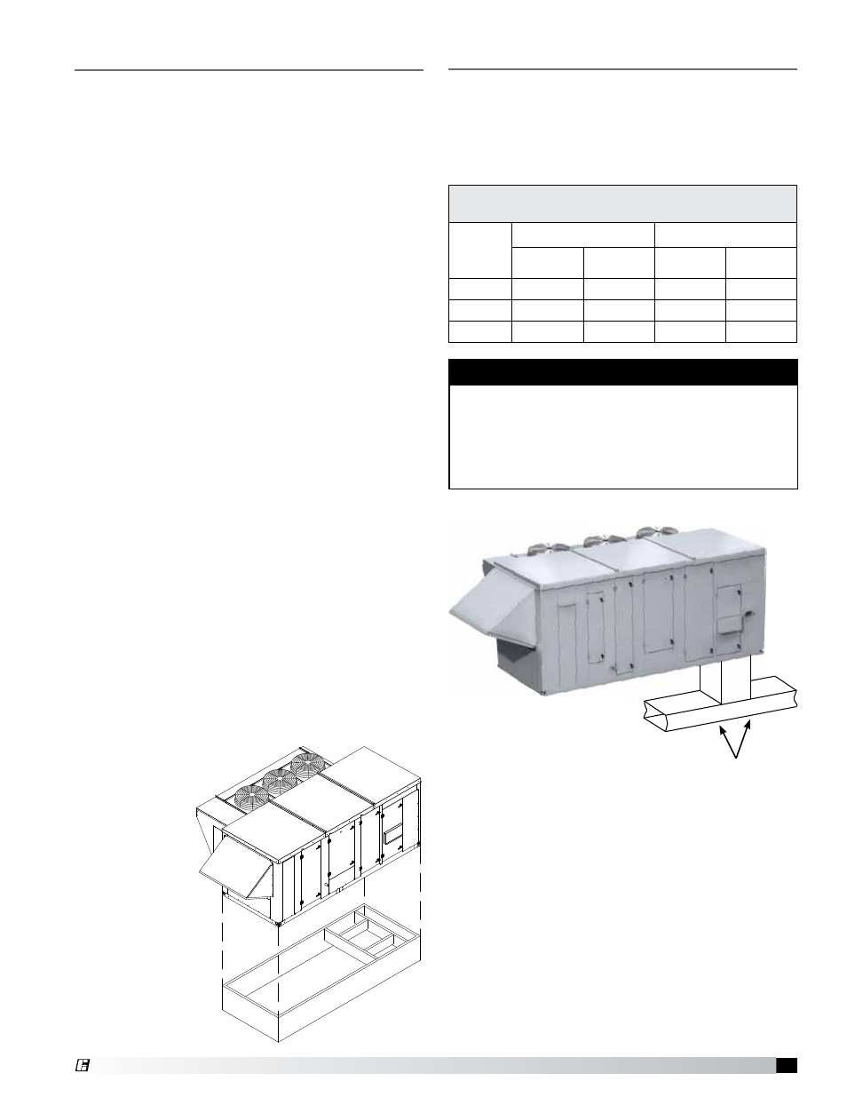
NOTE
Downblast Discharge Ductwork - whenever
downblast discharge is used, the ductwork directly
beneath the unit must be connected with either a “T”
or an “L” configuration and the area directly beneath
the heat source must not have any openings such
as louvers or grates.
7
Model MPX Make-Up Air Unit
®