Discharge air temperature sensor, Typical discharge air temperature sensor, Model mpx make-up air unit – Greenheck MPX (472695) User Manual
Page 10
Recommended Electrical and Gas
Connection Locations
Installation requires penetrations into the cabinet for
high voltage electrical supply, low voltage controller
circuitry and for gas supply.
Gas supply connections are made through the
side of each unit in the factory-provided openings.
Penetrations for electrical connections are to be made
in the field as job conditions may require. High voltage
supply wiring and low voltage controller circuitry
access may be made either through the side of the
unit or through the bottom. See illustrations below.
Recommended side access.
Recommended locations for access through the base
of the cabinet are as shown.
Furnace 1
Gas Input
Furnace 2
Gas Input
Electric Heater Power Input Connection
Access Side
Control Center Door
HIGH
VOLTS
LOW
VOLTS
Electrical Input
Access Side
NOTE:
ELECTRICAL SERVICE AREA
TWO PENETRATIONS ARE REQUIRED TO WIRE THE FIELD POWER
TO THE UNIT. THE FIELD POWER CONNECTION SHOULD ENTER
THE UNIT THROUGH THE FLOOR OR SIDE PANEL AND SHALL
CONTINUE INTO THE UNIT CONTROL CENTER. POWER WIRES
SHALL BE WIRED TO THE UNIT DISCONNECT. POWER WIRING
SHALL REMAIN IN THE APPROVED CONDUIT UNTIL IT ENTERS THE
UNIT CONTROL CENTER. ALL PENETRATIONS CUT INTO UNIT
SHALL BE SEALED TO PREVENT LEAKAGE.
MPX ELECTRICAL AND
GAS INPUTS ACCESS
SIDE
JAL
04/30/2010
1/20
MPX
P.O.BOX 410 SCHOFIELD, WISCONSIN 54476-0410
TITLE
DRAWN BY
ECO
B
ENG. REF.
DATE
SUPERSEDES
SCALE
CAD DRAWING NO.
DESCRIPTION
MAT'L
PART NO.
PAINT
GAUGE
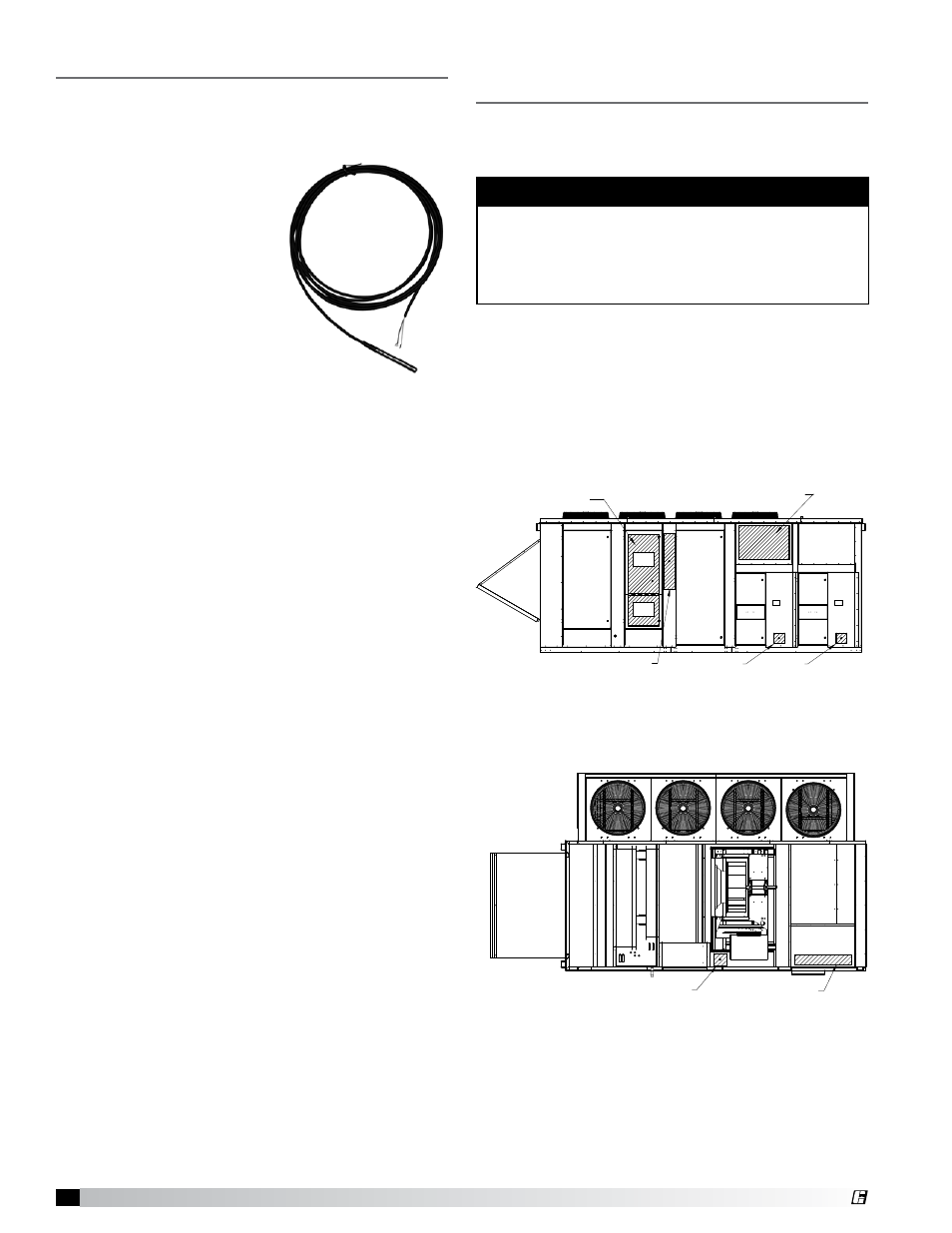
Discharge Air Temperature Sensor
All units are supplied with a Discharge Air Temperature
Sensor that is to be field-installed prior to unit start-
up. The sensor is to be installed at least three duct
diameters downstream of the
heat exchanger, or where good
mixed average temperature
occurs. The sensor must be
connected directly to the DDC
controller. All other sensors
and low voltage devices are
to be connected to the low
voltage terminal strip in the
control center. The discharge
air temperature sensor is
shipped loose and can be
found in the unit’s control
center. See the unit-specific
wiring diagram for connection
locations.
Typical Discharge Air
Temperature Sensor
WARNING
Do not make penetrations in the roof of the MPX for
any reason. High voltage wiring is located between
the inner and outer shells of the roof. Damage to the
roof wiring circuitry could result in serious bodily
harm.
NOTE:
ELECTRICAL SERVICE AREA
TWO PENETRATIONS ARE REQUIRED TO WIRE THE FIELD POWER
TO THE UNIT. THE FIELD POWER CONNECTION SHOULD ENTER THE
UNIT THROUGH THE FLOOR OR SIDE PANEL AND SHALL CONTINUE
INTO THE UNIT CONTROL CENTER. POWER WIRES SHALL BE WIRED
TO THE UNIT DISCONNECT. POWER WIRING SHALL REMAIN IN THE
APPROVED CONDUIT UNTIL IT ENTERS THE UNIT CONTROL
CENTER. ALL PENETRATIONS CUT INTO UNIT SHALL BE SEALED TO
PREVENT LEAKAGE.
Electrical Input
Base Access
Electric Heater
Power Input Connection
Base Access
MPX ELECTRICAL INPUTS
BASE
JAL
01/30/2010
1/20
MPX
P.O.BOX 410 SCHOFIELD, WISCONSIN 54476-0410
TITLE
DRAWN BY
ECO
B
ENG. REF.
DATE
SUPERSEDES
SCALE
CAD DRAWING NO.
DESCRIPTION
MAT'L
PART NO.
PAINT
GAUGE
10
Model MPX Make-Up Air Unit
®