Control centers, Main control center components, Furnace control center components – Greenheck MPX (472695) User Manual
Page 11
Control Centers
Each model has a main control center where high
voltage supply wiring and low voltage controller
circuitry is terminated. In addition, if the electric heat
option was selected, there will be a separate control
center for the electric heater where the dedicated high
voltage supply is terminated. If the optional indirect
gas-fired furnace option was selected, there will be a
furnace control center for each furnace.
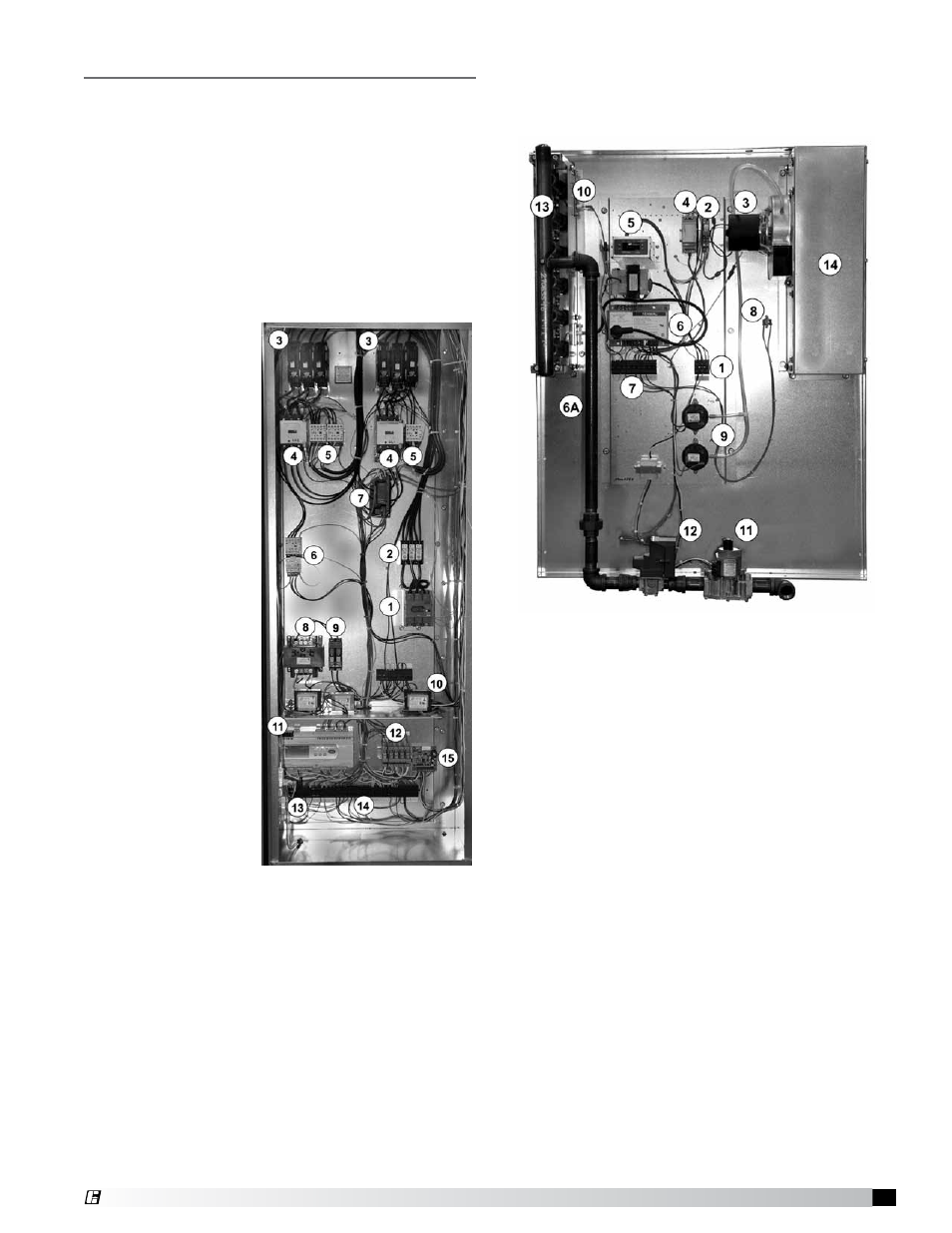
Main Control Center Components
(locations vary by model)
High Voltage Side
1. Lockable Main
Disconnect
(terminate high
voltage supply
here)
2. Power
Distribution
Blocks
3. Fuse Holders
4. Compressor
Motor
Contactors
5. Condensing
Fan Motor
Contactors
6. Supply Fan
Motor Starter
7. Digital
Compressor
Controller
(optional)
8. Indirect Gas
Furnace
Transformer
(optional)
9. Fuse Blocks
10. Step-Down
Transformers
(number varies)
Low Voltage Side
11. DDC Controller
12. Relays
13. Fan Proving Switch/Dirty Filter Switch
(on side wall)
14. Low Voltage Terminal Strip
15. Hot Gas Reheat Controller (optional)
NOT SHOWN: Phase Monitor (see page 13)
In all cases, refer to the unit-specific wiring diagram
located on the control center door.
Furnace Control Center Components
(component locations will vary)
Components shown are for a typical 4:1 turndown
configuration.
High Voltage Side
1. Power Distribution Block
2. Inducer Relay (controls combustion fan)
3. Combustion Blower
Low Voltage Side
4. Input Converter
5. FX05 Controller (modulates heat and switches
entire unit on/off
6. Spark Generator (also has high voltage present)
6A. Spark Igniter
7. 24 volt Terminal Strip
Control Sensors
8. Hi Temp Sensor (auto reset)
9. Air Flow Switches
10. Flame Sensor
Gas Train
11. Combination Valve
12. EXA Valve
13. Burner Manifold
14. Collector Box
11
Model MPX Make-Up Air Unit
®