Electrical connections, Sequence for wiring minivent unit, Frost control – Greenheck MiniVent (459023) User Manual
Page 7: Frost control test procedure
Energy Recovery Ventilator
7
®
Electrical Connections
Before connecting power to the unit, read and
understand the following instructions and wiring
diagrams. Complete wiring diagrams are attached inside
the blower door of the unit.
All wiring should be done in accordance with the
National Electrical Code ANSI/NFPA 70 latest edition
and any local codes that may apply. In Canada, wiring
should be done in accordance with the Canadian
Electrical Code. The equipment must be properly
grounded.
Electrical
Connection
Wheel and Filter Access
A
B
Sequence for wiring MiniVent unit:
1. The unit’s nameplate contains the voltage and total
amperage required. The wire supplying power to
the unit should be sized accordingly.
2. The main power line should be connected to the
appropriate terminal blocks.
Power may be routed to the MiniVent through the
opening on the underside of the unit. The locations
for the opening are provided in the figure to the
right.
3. Refer to the wiring diagrams in this manual or in the
unit for controlling the MiniVent.
Electrical Connection Location
MiniVent
A
B
450
21.875
12.5
750
28.375
15.5
All dimensions are in inches.
Caution
If any of the original wire must be replaced, the
replacement wire must have a temperature rating of at
least 105ºC.
DANGER
High voltage electrical input is required for this
equipment. This work should be performed by a
qualified electrician.
Frost Control
Extremely cold outdoor air temperatures can cause
moisture condensation and frosting on the energy
recovery wheel. Frost control is an optional feature that
will prevent/control wheel frosting.
1. Timed Exhaust frost control
This option is provided with a thermodisc mounted in
the outdoor air intake compartment.
Timed exhaust frost control includes a timer in
addition to the thermodisc. When timed exhaust frost
control is initiated, the timer will turn the supply blower
off. Time exhaust using default timer setting will shut
down the supply fan for 5 minutes every 30 minutes
to allow exhaust to defrost energy wheel. Use the test
procedure for troubleshooting.
Frost Control Test Procedure
1. Remove power from unit.
2. Jumper the temperature indicating thermodisc in
the unit control center. Thermodisc has a pre-set
temperature of 5ºF.
3. Set the frost control timer scale for T1 and T2 to 1m.
Set the timer settings for T1 and T2 to 10.
4. Add power to the unit. Blower should cycle on for
one minute, then turn off for one minute.
5. Remove power from unit and remove jumpers that
were placed. Re-set timer settings.
• T1 timer setting set to 5 and timer scale set to
10m for 5 minutes of wheel off time.
• T2 timer setting set to 5 and timer scale set to
1h for 30 minutes of wheel on time
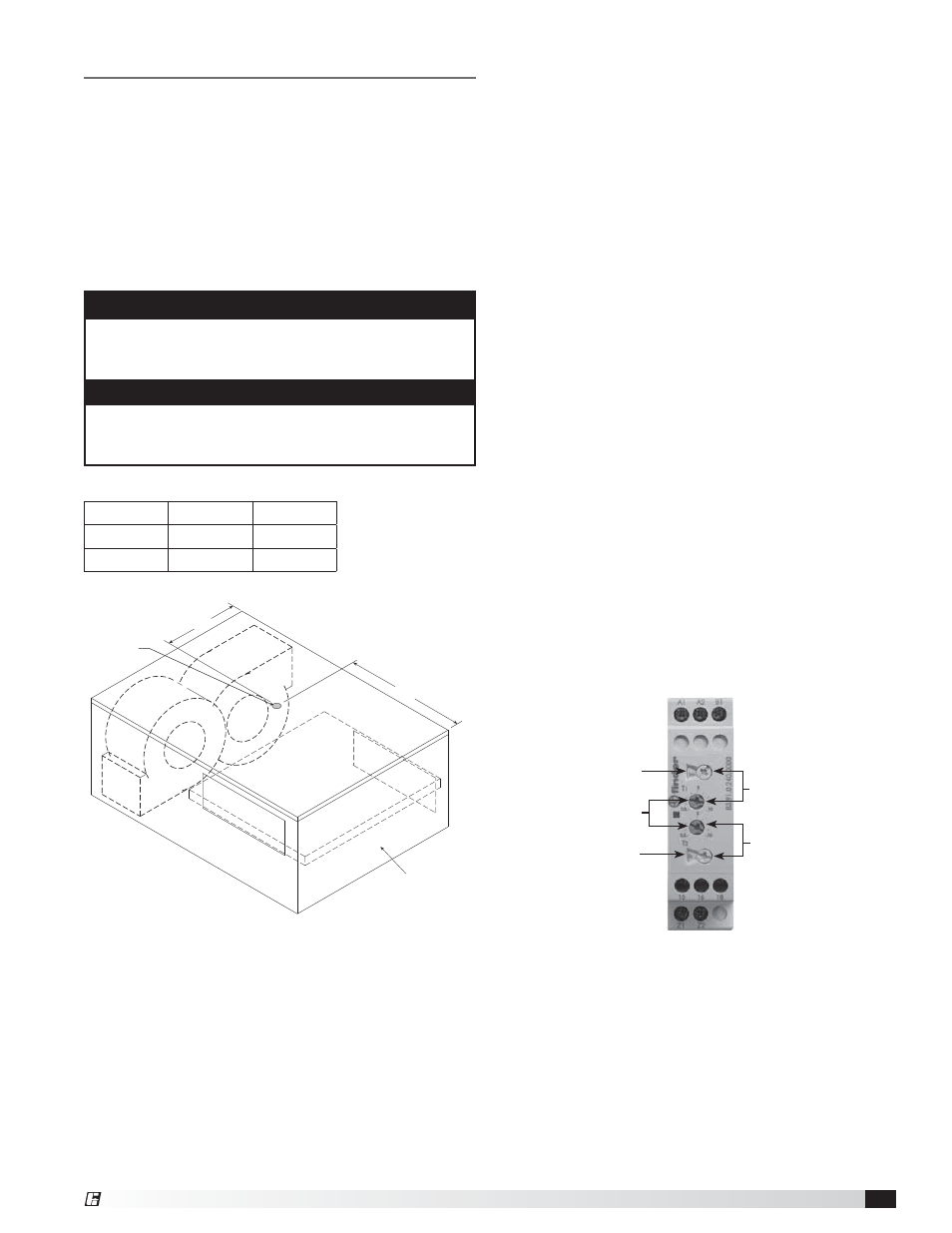
Timer
Scale
Timer
Scale
Timer
Settings
T1
T2