Greenheck MiniVent (459023) User Manual
Page 3
Energy Recovery Ventilator
3
®
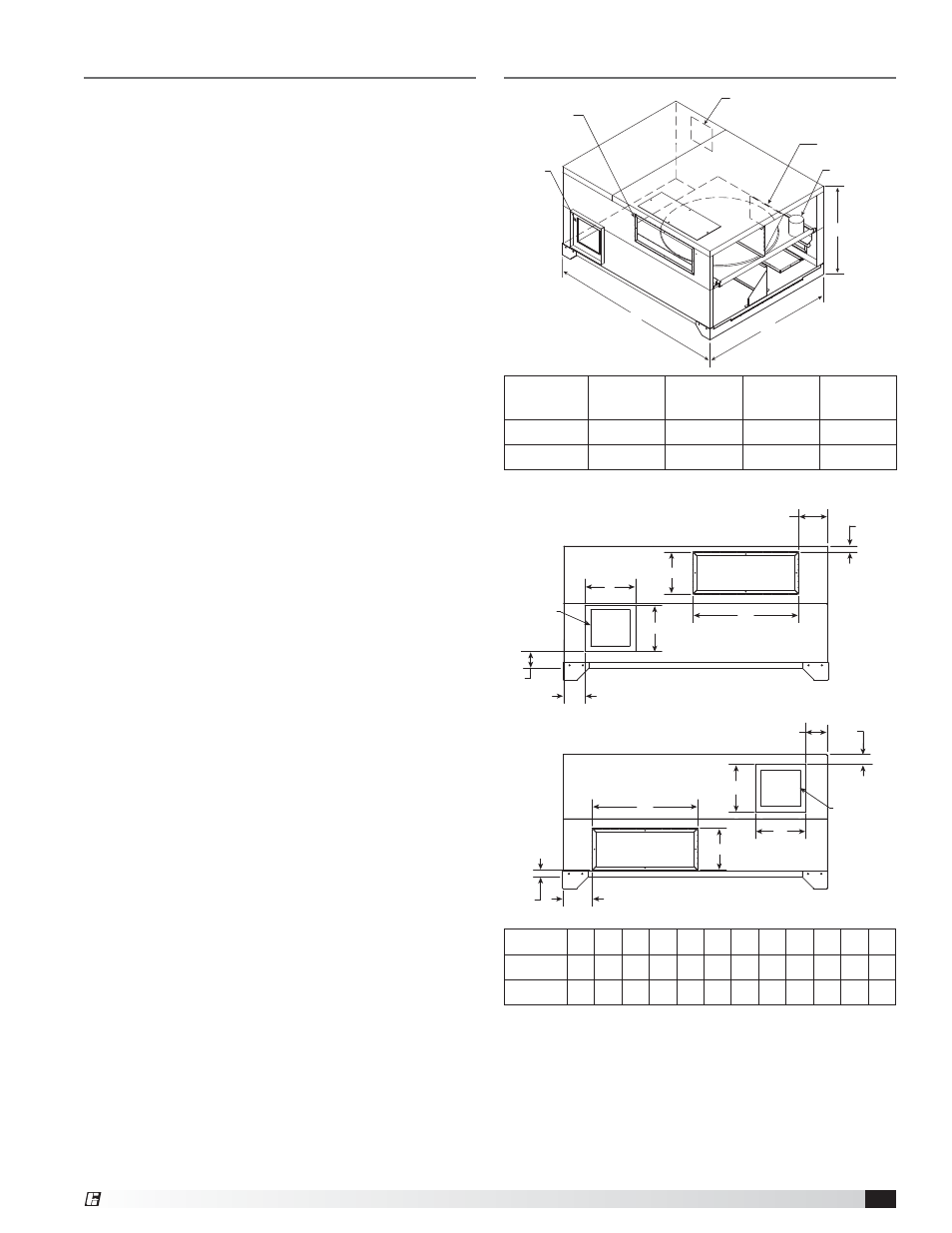
Dimensional Data and Weights
C
Energy Wheel
B
A
Fr
ont V
iew
Back V
iew
Intake
Side "B"
Discharge
Side "B"
Discharge
Side "A"
Intake
Side "A"
MiniVent
A
B
C
Weight
(lbs.)
450
40.2
28.6
19.9
160
750
45.8
35.3
23.8
240
All dimensions are in inches.
MiniVent D
E
F
G
H
J
K
L
M
N
P
Q
450
10
8
12
6
4.3 1.4
6
1.5
6
1
4.8 3.4
750
10 10 18
7
4
2.2 5.1 1.5 5.1 1.1
4
1.5
All dimensions are in inches.
Table of Contents
Dimensional Data and Weights . . . . . . . . . . . . . . . . . . . 3
Service Clearances and Access Panel Locations . . . . . 4
Intake and Discharge Locations . . . . . . . . . . . . . . . . . . 4
Installation
Hang Mounting with Hanging Vibration Isolators . . . 5
Base Mounting with Base Vibration Isolators . . . . . . 6
Duct
Connections
. . . . . . . . . . . . . . . . . . . . . . . . . . . 6
Electrical Connections . . . . . . . . . . . . . . . . . . . . . . . . . 7
Frost
Control
. . . . . . . . . . . . . . . . . . . . . . . . . . . . . . . 7
Wiring Schematics . . . . . . . . . . . . . . . . . . . . . . . . . . 8-9
System Start-Up
Pre-Start-Up
Checklist
. . . . . . . . . . . . . . . . . . . . . . 10
Unit
Documentation
Record
. . . . . . . . . . . . . . . . . . 10
Unit Start-Up Checklist . . . . . . . . . . . . . . . . . . . . . . 11
General
. . . . . . . . . . . . . . . . . . . . . . . . . . . . . . . . . . 12
Energy
Wheel
. . . . . . . . . . . . . . . . . . . . . . . . . . . . . 12
Blower Wheel Rotation . . . . . . . . . . . . . . . . . . . . . . 12
Fan
RPM
. . . . . . . . . . . . . . . . . . . . . . . . . . . . . . . . . 12
Motor
. . . . . . . . . . . . . . . . . . . . . . . . . . . . . . . . . . . . 12
Routine Maintenance
General
. . . . . . . . . . . . . . . . . . . . . . . . . . . . . . . . . . 12
Fasteners and Set Screws . . . . . . . . . . . . . . . . . . . 12
Removal of Dust and Dirt . . . . . . . . . . . . . . . . . . . . 12
Internal
Filters
. . . . . . . . . . . . . . . . . . . . . . . . . . . . . 12
Energy
Wheel
Maintenance
. . . . . . . . . . . . . . . . 12-13
Troubleshooting . . . . . . . . . . . . . . . . . . . . . . . . . . . . . . 14
Optional Vari-Green
®
EC Motors . . . . . . . . . . . . . . . . 15
Maintenance Log . . . . . . . . . . . . . . . . . . . . . . Backcover
Our Commitment . . . . . . . . . . . . . . . . . . . . . . Backcover
Intake and Discharge positions are not labeled because
they are configurable by rotation of the unit about the
vertical axis. The supply and exhaust can be on either
side, but the intake/discharge relationship must be
maintained. For example, Outdoor Air Intake = Intake
Side “B”/Outdoor Air Discharge = Discharge Side “B”.
The preferred configuration is to have the energy wheel
motor in the exhaust airstream.
L
K
F
G
D
E
J
H
P
Q
D
E
F
G
N
M
INTAKE
SIDE "A"
DISCHARGE
SIDE "A"
INTAKE
SIDE "B"
DISCHARGE
SIDE "B"
FRONT VIEW
BACK VIEW