Set the maximum firing rate, Important, Set the minimum firing rate – Greenheck DG / DGX with Direct Spark (470652) User Manual
Page 17: Set the low fire time delay, Direct gas nameplate, Combined regulator valve, Modulating valve
Direct Spark Ignition Make-Up Air
17
®
5. Set the Maximum Firing Rate
Monitor the unit’s actual temperature rise by placing
a thermocouple in the unit’s inlet and a second in the
discharge, three duct diameters downstream of the burner.
Send the unit to maximum fire by disconnecting and
isolating the wire connected to Terminal 3 on the
Maxitrol 14 or the Maxitrol 44. See images on next page.
While monitoring the unit’s temperature rise, set the
maximum firing rate by adjusting the regulator until the
designed temperature rise is achieved. After setting the
maximum firing rate, reconnect the wire to the amplifier.
Direct Gas Nameplate
NOTE
The low fire time delay must be set high enough to
provide at least 10 seconds of low fire while the unit
tries to light.
IMPORTANT
Setting the maximum firing rate during mild weather
conditions may cause the high limit to trip out during
extreme conditions requiring manual resetting.
NOTE
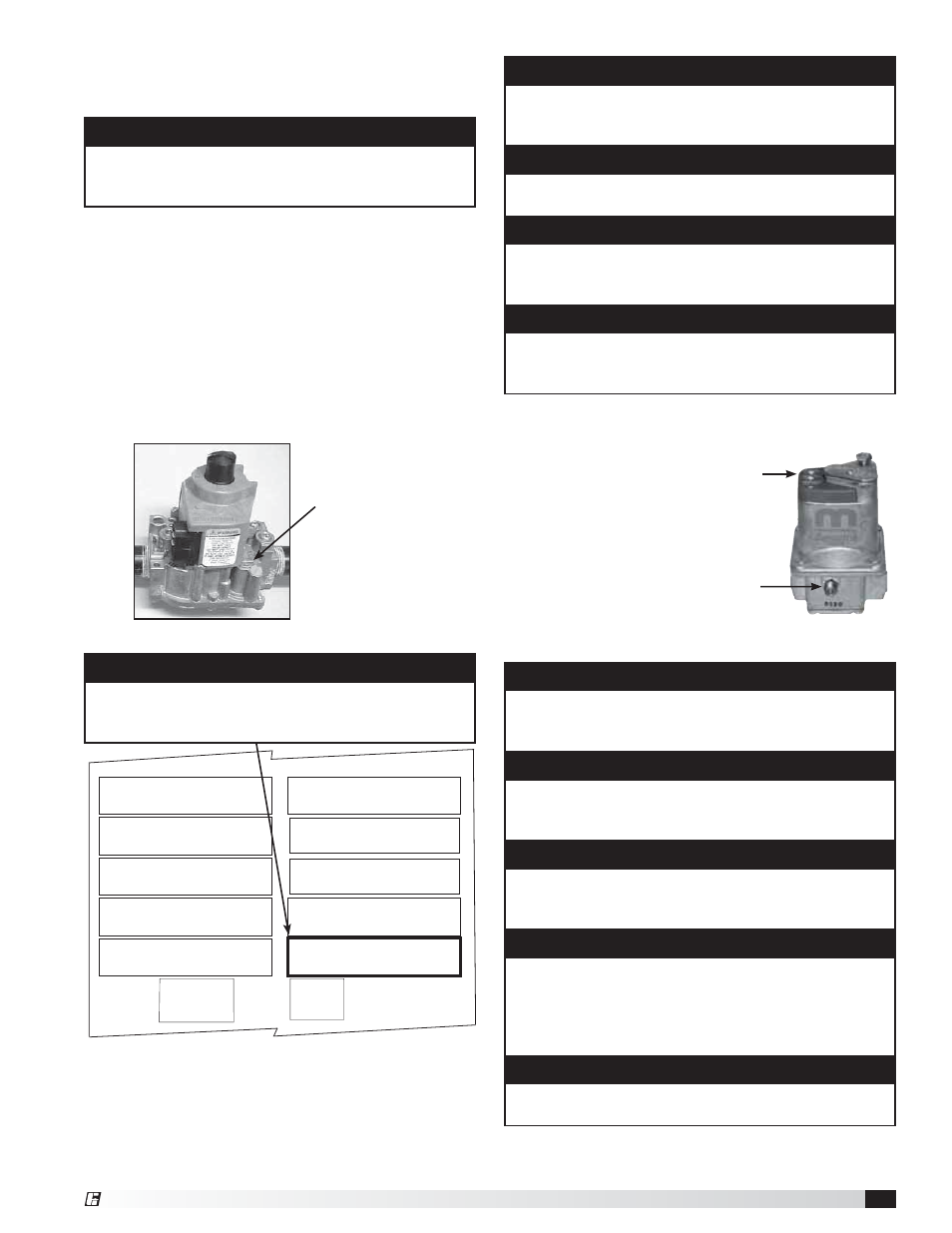
Gas trains are equipped with a combined regulator
valve.
NOTE
Clockwise rotation increases the temperature rise,
counterclockwise rotation decreases the temperature
rise.
NOTE
The minimum setting for the maximum firing rate may
be higher than required. This is acceptable, the burner
will modulate as needed.
IMPORTANT
The proper minimum firing rate setting results in a
small ribbon of continuous flame which covers the
flame rod and runs across the entire burner.
IMPORTANT
The minimum firing rate setting is critical. If the
settings is too high, the unit may not light, too low and
the flame rod may not detect the flame.
IMPORTANT
Do not allow the disconnected wire to come in
contact with a potential ground. Damage to the
amplifier or transformer could result.
NOTE
Adjusting the maximum and minimum fire may require
the inlet air sensor to be initially set higher than
desired in order to start the burner(s). Once high and
low fire have been set, the inlet air sensor should be
turned down to the desired temperature.
NOTE
Counterclockwise rotation increases the minimum fire
rate setting, clockwise rotation decreases the setting.
6. Set the Minimum Firing Rate
Disconnect and isolate one of the wires running to the
modulating valve to
send the unit to its
minimum firing rate.
Set the minimum
firing rate by
adjusting the needle
valve.
After setting the
minimum firing rate,
reconnect the wire to
the modulating valve.
Maximum firing rate
adjustment
Combined Regulator Valve
4. Set the Low Fire Time Delay
Set the low fire time delay to 75% of its maximum setting.
See below for the location of the time delay setting.
Minimum firing
rate adjustment
Remove one wire
to send the unit
to the minimum
firing rate.
Modulating Valve
“ W.C.
“ W.C.
“ W.C.
F
PSI
“ W.C.
“ W.C.
MAX BTU/HR
BTU/H MAX
NORMAL MANIFOLD
PRESSURE
PRESSION D’ADMISSION
NORMALE
MIN GAS
PRESSURE
PRESSION DE GAZ
MIN BURNER
PRESSURE DROP
PERTE MIN DE PRESSION
DANS LE BRULEUR
TYPE OF GAS
NATURE DU GAZ
MIN BTU/HR
BTU/H MIN
MIN GAS PRESSURE
FOR MAX OUTPUT
PRESSION DE GAZ MIN
POUR PUISSANCE MAX
MAX BURNER
PRESSURE DROP
PERTE MAX DE PRESSION
DANS LE BRULEUR
MAX GAS
PRESSURE
PRESSION DE GAZ
MAX
DESIGN ΔT
ΔT NORMALE
EQUIPPED FOR
CONCU POUR
SCFM
“ W.C.
EXTERNAL STATIC PRESSURE
PRESSION STATIQUE EXTERIEURE
AGAINST
CONTE
NOTE
Do not set the burner maximum firing rate based on gas
pressure. It should be set based on the unit’s designed
temperature rise shown on the direct gas label.