Side panel, Rear panel – Genee World GV-8100 User Manual
Page 9
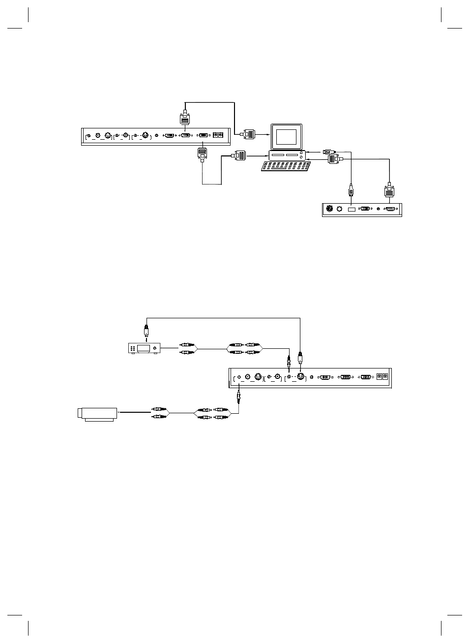
Step 2: Connect to the projector.
Connect visualiser’s PROJECTOR port to the RGB IN port of the projector
port with the RGB cable provided together the visualiser.
If you need control a projector with the visualiser, please use the projector
RS232 cable (6-pin to 9-pin) to make the connection between the projector
and the visualiser. Some projector models may require a converter cable in
addition to this standard RS232 cable to connect to the projector
control port, for the pin locations and shape of some projectors’ control
port connector may be different from the connector of a standard RS232
cable. After the visualiser is connected to the projector, you can control
projector’s power on, standby and input selection with the visualiser. (For
projectors other than Hitachi, the Code Writing program that comes with
the visualiser is required for this function.)
Projector
RGB
Input
Screen
RS232
Cable
Side Panel
MIC
PROJECTOR
USB
RGB IN
AUDIO IN
RS232
PROJECTOR
Rear Panel
S-VIDEO
OUT
AUDIO VIDEO
OUT
AUDIO
AUDIO VIDEO
IN
S-VIDEO
IN
AUDIO IN
OUT -COMPUTER- IN
OUT-12V- IN
2. Connect the RS232 cable to the computer’s connector. The visualiser’s RS232 port is
located on its right side.
3. After completion of the connection, turn on the visualiser
click [start] -> [All Programs] -> Visualiser -> and the following dialogue box appears
as below:
When the indicator of “Current RS-232 Connection Status” is green, that means the
connection between the visualiser and the computer’s RS232 connector is good. If the
indicator is red, please check if the RS232 cable is connected correctly. When all the
cables are connected correctly, please click “Projector” to select your projector model
under the drop-down list, then click “Send”. If you can not find your particular projector
model in the “Projector”, please do the following:
1) Select “Baud rate” and “parity” and input the projector control code. (The baud
rate, parity and control code is supplied by projector’s manufacturer, please refer to the
projector’ manual)
Note: You can connect a laptop computer to the RGB IN port of side panel with a
RGB cable.
Step 4: Connect video equipment with S-Video input.
Output of the S-Video signal from the visualiser to the projector is already done
in the step 2, where the RGB cable comes out from the visualiser and goes to the
projector. After the connections as steps 2, 3, 4 are made, input signals from the
computer, visualiser CCD and S-Video are going to the RGB1 input on the projector
and will be displayed on the projector screen as RGB1. These signals can be seen in
turn when pressing “CCD/PC1/PC2” and “S-VIDEO/VIDEO” on the control panel of
the visualiser.
Remarks: RGB IN signal can not go to S-VIDEO OUT or VIDEO
RS232
Cable
MIC
PROJECTOR
Computer
USB
RGB IN
AUDIO IN
RS232
Side Panel
RGB Output
To the
Monitor
USB Connector
AUDIO IN
OUT
AUDIO VIDEO
OUT
VIDEO
AUDIO
S-VIDEO
IN
S-VIDEO
AUDIO
IN
PROJECTOR
OUT -COMPUTER- IN
OUT-12V- IN
Rear Panel
AUDIO
IN
S-VIDEO
OUT
OUT
VIDEO
AUDIO VIDEO
Video equipment
S-Video out
Audio out
Audio input
(or amplifier/speaker equipment)
Projector
S-Video Cable
S-VIDEO
AUDIO
IN
PROJECTOR
Rear Panel
AUDIO IN
OUT-12V- IN
OUT -COMPUTER- IN
computer connected with a USB connector.
Click [Start] -> [Program] -> [VideoCap] -> “VideoCapx.xx” (x.xx is software’s version)
to open the software.
A. Static Images Snap
Click “Capture”—>“Capture Frame”, input the file name in dialogue box, or you can click
icon on the toolbar, then input file name in dialogue window. The image file is
JPG
format.
B. Snap Video Stream
Click “Capture”—> “Start Capture”, input the file name in dialogue box, or click
icon on the toolbar, then input the file name in dialogue box. If you want to set the
time limit for the capture, select “Capture” ->“Set Time Limit” to set the time limit. Click
“Start Capture” to start capture, and click “Stop Capture” or “ ” icon on the toolbar to
stop
capture. (If you have set the time limit, it will stop automatically when the time is up.)
The video file is AVI format.
C. Set the Frame Rate
Click [Capture] -> [Set Frame Rate], and click open “Choose Frame Rate” to set the
frame rate.
D. Set Time Limit
Click [Capture] -> [Set Time Limit] to set the time limit while capturing video.
CONTROLLING PROJECTOR WITH VISUALISER
The code writing software is used to inputting projector’s control code, then can control
various projector with the visualiser.
1. Connect the visualiser to the projector with the RGB�VIDEO�S-VIDEO cables.
Step 3: Connect to a desktop computer.