Po w e (“-“ is space is enter.), Side panel – Genee World GV-8100 User Manual
Page 23
BASIC PREPARATIONS
1. Use one hand to hold the base of the visualiser, use the other hand to carefully lift
up the camera stand of the unit.
2. Open the arm lights and rotate the camera head until they are in proper positions.
3. Making connections:
Before making any connection, turn off all the power, including power of the visualiser
and the equipment to be connected.
Step 1: Connect power source.
First connect the power cord to the 12V IN connector.
The input format of projector’s control code is as follows:
a. If the data is in the numerical value format, please input data directly, block
them off with comma, do not distinguish lowercase and uppercase.
In the POWER ON box, input ’POWER 1’, 0d, 0a
(Remarks: There are 3 spaces after POWER, 0d, 0a is enter.)
Input other codes in the same way.
c. If the data is in the numerical value and character format, then synthesize
the above-mentioned formats.
3) Once done, click “Add” to add your projector model, then Click “Send”.
Afterward, click “Ok”. Now, you can use the visualiser to control your projector.
4. Connect the visualiser’s projector control port to the RS232 port
For example: the “POWER ON” code in Hitachi projector manual is :
In the POWER ON box, Input : be, ef, 03, 06, 00, ba, d2, 01, 00, 00, 60, 01, 00. Then use
the same input rule to input other code.
b. If the data is in the character string format, input ‘character string’.
For example: the “POWER ON” code in the SHARP C40/50 projector manual is :
BE EF 03 06 00 BA D2 01 00 00 60 01 00
P
O W E - - - 1
(“-“ is space is enter.)
TELE/ WIDE (Increase and decrease the magnification)
FAR/NEAR (Focus near or far)
VOL+/VOL- (Increase or decrease the volume)
CCD/PC1/PC2 (CCD/RGB input signal selection)
VIDEO (Video input signal selection)
RED +/- (Increase/decrease the red hue)
BLUE +/- (Increase/decrease the blue hue)
BRIGHT +/- (Increase/decrease the brightness)
SCROLL / (Move the image up/down)
Remarks: FREEZE, TITLE, D./S. and SPLIT functions are only
available on PROJECTOR OUT port.
CONNECTIONS
USB
PROJECTOR MIC
VIDEO
OUT
AUDIO
AUDIO
OUT
S-VIDEO
IN
VIDEO
RGB IN
AUDIO IN
RS232
Side Panel
8
PROJECTOR
OUT -COMPUTER- IN
OUT-12V- IN
AUDIO IN
S-VIDEO
7
AUDIO
IN
18
with a RS232 cable Please disconnect the computer from the RS232 port first. Then
use buttons on the operation panel to control the projector.
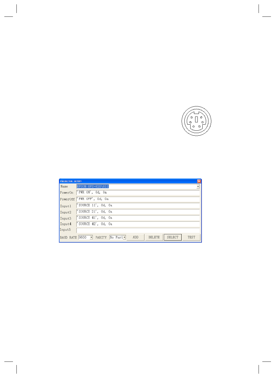
The visualiser provides a 6-pin to 9-pin RS232 cable. If this cable does not match
to your projector’s RS232 port, an additional RS232 cable is needed. This additional
RS232 cable can be made based on the pin location of the projector’s RS232 con-
trol port. The pin locations of the visualiser are: the pin 1 is RXD (Received Data);
the pin 5 is TXD (Transmitted Data); the pin 4 is GND (Ground). Other pins are not
defined. The pin location information of the projector is provided by the projector’s
manufacturer. The projector’s RS232 control port normally has RXD pin, TXD pin
and GND pin, the name may be different. The parallelism of each data pin is shown
as follows:
Visualiser’s RXD pin------------Projector’s TXD pin
Visualiser’s TXD pin------------Projector’s RXD pin
Visualiser’s GND pin------------Projector’s GND pin
5. If you can not use buttons on the operation panel to control the projector,
please use Code-Writing software’s projector control code testing function to check
if the control code is correct.
Click “Projector” button, the following dialogue box appears as below:
Connect the visualiser to a computer with a RS232 cable (Please
6
5
4
3
2 1