Assembly instructions – GAMMA 5800 Els STRINGING MACHINE 6 POINT SC MOUNTING (Issue 3 - January 2009) User Manual
Page 5
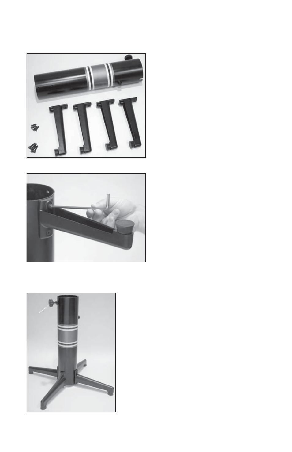
Base Leg Assembly
The stringing machine uses a four leg floor
stand design. The legs must be assembled
to the lower column before use. Remove all
parts from the shipping carton to confirm that
contents match the list of parts on Page 3.
Base Leg Assembly (Cont.)
Align the holes in the leg flange with the
matching holes in the lower column. Secure
the leg with one M8 FLAT HEAD screw
through the upper hole, and one M8 SOCKET
HEAD cap screw through the bottom hole.
Install one 8mm nut on each screw. Repeat
this procedure for the three remaining legs.
ASSEMBLY INSTRUCTIONS
Base Leg Assembly (Cont.)
To complete the floor stand, screw the height adjust-
ment locking knob (“A”) into the side of the lower column.
The locking knob should not protrude beyond the inside
of the lower column at this time.
“A”
4
- 5800 Els STRINGING MACHINE 2 POINT SC MOUNTING (Issue 2 - January 2009) 8800 Els STRINGING MACHINE 2 POINT SC MOUNTING (Issue 2 - January 2009) 6900 Els STRINGING MACHINE 2 POINT SC MOUNTING (Issue 4B - February 2014) 6900 Els STRINGING MACHINE 6 POINT SC MOUNTING (Issue 5A - February 2014) 6900 Els STRINGING MACHINE 2 POINT SC MOUNTING (Issue 2 - August 2010) 6900 Els STRINGING MACHINE 2 POINT SC MOUNTING (Issue 1 - April 2010) 8800 Els STRINGING MACHINE 6 POINT SC MOUNTING (Issue 2 - January 2009) X-Stringer X-Els STRINGING MACHINE (Issue 1A - September 2010) PROGRESSION Els STRINGING MACHINE (Issue 1A - September 2010) PROGRESSION Els STRINGING MACHINE (Issue 3A - February 2014) X-Stringer X-Els STRINGING MACHINE (Issue 3A - February 2014) 6900 Els STRINGING MACHINE 6 POINT SC MOUNTING (Issue 1 - April 2010)