Installation – GAI-Tronics XCP0400A ICP9000 Upgrade Kit User Manual
Page 2
Pub. 43003-032C
Model XCP0400A CommandPLUS Console Upgrade Kit
Page: 2 of
3
f:\radio products-draft\gtc 43003\43003-032c\43003-032c.doc
12/10
Installation
CommandPLUS Series Desktop Console
1. Disconnect power from the CommandPLUS Series Desktop Console and remove all attached cables
from the rear of the console.
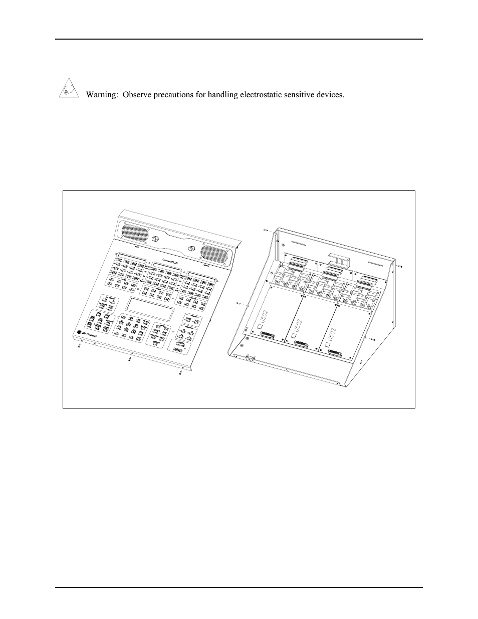
2. Remove the seven screws securing the top panel and gently lift the cover exposing the attached
speaker cable and master display cable. See Figure 1.
Figure 1.
3. Disconnect the speaker cable at the male-to-female connection point. Unplug the master display
cable from the top cover.
4. On each slave PCBA (CP-CSD) locate U502 EPROM socket and extract the EPROM.
5. Replace them with the Slave EPROM (SLAV**) provided in this kit, taking care to observe the
direction indicated on the socket of the EPROM. Ensure that the chip is properly seated in the socket.
6. Disconnect the ribbon cables (SLV-CBL-M) attached to the Main PCBA.
7. Remove the four screws attaching the mounting plate to the base.
8. Disconnect the (SLV-CBL-P) cables from the surge suppression PCBAs. This allows you to remove
the mounting plate giving access to the main control PCBA. See Figure 1.
- 370-201, 372A Interface Amplifier Assembly (10 pages)
- 13314-001 and 13314-002 Div. 2 Hazardous Area Speaker Assembly using 13314 Driver (3 pages)
- 230-001 Pole-Mounting Kit (3 pages)
- Electro Sound Electro-Sound Communication System (9 pages)
- 13314-004 Div. 2 Hazardous Area 100-Volt Horn Driver (5 pages)
- XGM003A Gooseneck Microphone Kit (5 pages)
- XGM003A Gooseneck Microphone Kit (2 pages)
- XGM003A Gooseneck Microphone Kit (26 pages)
- 9974 Junction Box (5 pages)
- 232-001 Pole Mounting Kit (3 pages)
- 13411-001 and 13411-002 Replacement Voice Coil / Diaphragm Assemblies (5 pages)
- 726-101 Single Party Desktop Subset (5 pages)
- 726-101 Single Party Desktop Subset (4 pages)
- 478-002 Centra-Page Desktop Subset (6 pages)
- 210-001 Corridor Telephone (10 pages)
- 239WM-002 Slim Wall-Mount Stanchions (10 pages)
- 239WM-002 Slim Wall-Mount Stanchions (5 pages)
- 239WM-002 Slim Wall-Mount Stanchions (6 pages)
- 239WM-002 Slim Wall-Mount Stanchions (4 pages)
- 239WM-002 Slim Wall-Mount Stanchions (4 pages)
- Speaker / Horn Installation for GAI-Tronics Communication System (8 pages)
- 700 Series 120 V AC Page/Party Systems (10 pages)
- 700 Series 24 V DC Page/Party Systems (14 pages)
- 703-002 Multi-Party 24 V DC Amplifier Enclosures (13 pages)
- 703A Indoor Multi-Party 115 V AC Amplifier Enclosure (3 pages)
- 703A Indoor Multi-Party 115 V AC Amplifier Enclosure (8 pages)
- 723-001 Remote Handset / Speaker Amplifier (3 pages)
- 723-003 24 V DC Remote Handset/Speaker Amplifier (7 pages)
- 237-001 Plug-in Power Supply for Telephones (3 pages)
- 733-002 Single Party 24 V DC Amplifier Enclosure (13 pages)
- 7855-001 Explosion-proof Handset Stations (13 pages)
- 7855-002 24 V DC Explosion-proof Page/Party Handset Stations (14 pages)
- 670-001 Explosion-proof Page/Party Speaker Station (9 pages)
- 670-002 24 V DC Explosion-proof Page/Party Speaker Station (10 pages)
- 13351 Integral Loudspeakers (5 pages)
- 305-001 Line Balance Assembly (3 pages)
- 272-001 Intrinsically-Safe Telephones (13 pages)
- 713-102 24 V DC Page/Party Remote Speaker Amplifier (5 pages)
- 263-000 Isolation Barrier Unit (I.S. Phone) (14 pages)
- 774-001 Portable Station Enclosure (Page/Party) (5 pages)
- 234SBA 234SBA Stanchion Broadcast Assembly (12 pages)
- 491-204 Mine Dial / Page Phone (10 pages)
- 773-001 Outdoor Jack Station (Page/Party) (3 pages)
- 491 Series Mine Dial / Page Phone Interface Cabinet (23 pages)
- 268-001 Intrinsically-Safe Telephone Rack-Mount System (14 pages)