GAI-Tronics XCP0060A External Enhanced Full Duplex Phone Interface Field Kit User Manual
Page 4
Pub. 43003-017C
Model XCP0060A External Full Duplex Phone Interface Kit
Page: 4 of 5
11/02
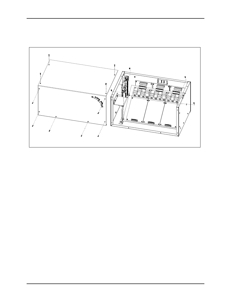
3. Remove the 10 screws securing the side cover panel and gently lift the cover off. See Figure 4.
4. Remove the 4 screws attaching the mounting plate to the main enclosure. This allows you to remove
the mounting plate giving you access to the main control PCBA. See Figure 4.
5. Remove the screw in the center of the main control PCBA. Screw in one of the supplied #4-40
male/female standoffs. See Figure 3.
6. Attach the remaining two standoffs in the two open holes highlighted by circles on the main control
PCBA. Place the threaded side through the holes and attach the supplied #4-40 nuts to the underside.
See Figure 3.
7. Place the CTH PCBA on the standoffs and attach with the supplied #4-40 screws. The J13 connector
plugs into the P13 connector on the main control PCBA. See Figure 3.
8. Attach the supplied ground cable to the ground screw located on the rear panel. Attach the other end
to the quick-disconnect on the CTH PCBA.
9. After the PCBA has been properly mounted, you may reassemble the MCU by reversing the
disassembly procedure. Verify that all CSD-to-main board ribbon cables are properly positioned into
their protective guides and connected to their respective main board connectors.
Other Connections
If this equipment is to be interfaced with an existing 911 PABX, the 8-pin modular connector supports the
incoming ringing closure input from the PABX, and the off-hook closure output to the PABX. Standard
8-pin modular plug tooling can be used to interface to the PABX. Refer to the table below for cable
pinout.
Figure 4.