Installing the 70v/100v option – GAI-Tronics 12832-002 Zone 2/22 ICS 70V/100V Upgrade Kit User Manual
Page 2
Pub. 42003-271A
M
ODEL
12832-002
Z
ONE
2/22
ICS
70
V/100V
U
PGRADE
K
IT
Page
2 of 5
f:\standard ioms - current release\42003 kit manuals\42003-271a.doc
03/14
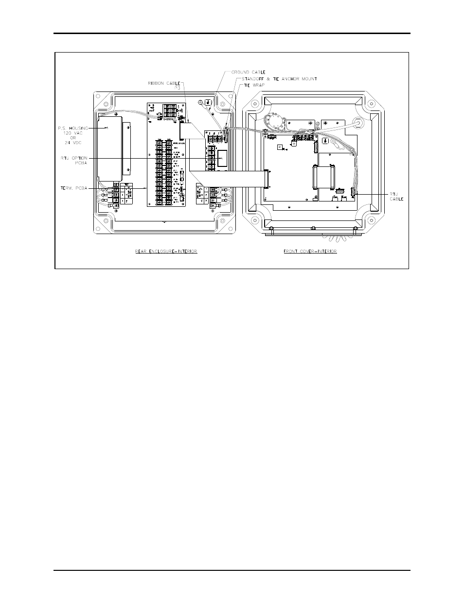
Figure 1. ICS Zone 2/22 Station – Interior View
Installing the 70V/100V Option
1. Cut the tie wrap that is securing the ground wire and RTU cable assembly (when applicable).
2. Remove standoff and tie anchor mount by removing the screw.
3. On the Termination PCBA, unplug the ribbon cable at P3 for easier access to the rear mounting plate.
4. When applicable, remove the four 4-40 screws that secure the RTU PCBA, the RTU PCBA and the
four 4-40
7/16-inch female/female standoffs from the rear mounting panel. Set these aside.
5. Attach two of the 4-40
1-3/16-inch male/female standoffs to the rear mounting panel. Attach the
bracket and toroid assembly to the rear mounting panel using the four 4-40 keps nuts if there is no
RTU option. See Figure 2.
6. If there is an RTU option, attach the bracket with two more 4-40
1-3/16-inch male/female standoffs.
Use the four 4-40
7/16-inch female/female standoffs to secure the bracket. Re-attach the RTU
PCBA to the standoffs and bracket using the 4-40 screws. See Figure 2.
- 370-201, 372A Interface Amplifier Assembly (10 pages)
- 13314-001 and 13314-002 Div. 2 Hazardous Area Speaker Assembly using 13314 Driver (3 pages)
- 230-001 Pole-Mounting Kit (3 pages)
- Electro Sound Electro-Sound Communication System (9 pages)
- 13314-004 Div. 2 Hazardous Area 100-Volt Horn Driver (5 pages)
- XGM003A Gooseneck Microphone Kit (5 pages)
- XGM003A Gooseneck Microphone Kit (2 pages)
- XGM003A Gooseneck Microphone Kit (26 pages)
- 9974 Junction Box (5 pages)
- 232-001 Pole Mounting Kit (3 pages)
- 13411-001 and 13411-002 Replacement Voice Coil / Diaphragm Assemblies (5 pages)
- 726-101 Single Party Desktop Subset (5 pages)
- 726-101 Single Party Desktop Subset (4 pages)
- 478-002 Centra-Page Desktop Subset (6 pages)
- 239WM-002 Slim Wall-Mount Stanchions (4 pages)
- 210-001 Corridor Telephone (10 pages)
- 239WM-002 Slim Wall-Mount Stanchions (10 pages)
- 239WM-002 Slim Wall-Mount Stanchions (5 pages)
- 239WM-002 Slim Wall-Mount Stanchions (6 pages)
- Speaker / Horn Installation for GAI-Tronics Communication System (8 pages)
- 700 Series 120 V AC Page/Party Systems (10 pages)
- 700 Series 24 V DC Page/Party Systems (14 pages)
- 703-002 Multi-Party 24 V DC Amplifier Enclosures (13 pages)
- 703A Indoor Multi-Party 115 V AC Amplifier Enclosure (8 pages)
- 703A Indoor Multi-Party 115 V AC Amplifier Enclosure (3 pages)
- 723-001 Remote Handset / Speaker Amplifier (3 pages)
- 723-003 24 V DC Remote Handset/Speaker Amplifier (7 pages)
- 237-001 Plug-in Power Supply for Telephones (3 pages)
- 733-002 Single Party 24 V DC Amplifier Enclosure (13 pages)
- 7855-001 Explosion-proof Handset Stations (13 pages)
- 7855-002 24 V DC Explosion-proof Page/Party Handset Stations (14 pages)
- 670-001 Explosion-proof Page/Party Speaker Station (9 pages)
- 670-002 24 V DC Explosion-proof Page/Party Speaker Station (10 pages)
- 13351 Integral Loudspeakers (5 pages)
- 305-001 Line Balance Assembly (3 pages)
- 272-001 Intrinsically-Safe Telephones (13 pages)
- 713-102 24 V DC Page/Party Remote Speaker Amplifier (5 pages)
- 263-000 Isolation Barrier Unit (I.S. Phone) (14 pages)
- 774-001 Portable Station Enclosure (Page/Party) (5 pages)
- 234SBA 234SBA Stanchion Broadcast Assembly (12 pages)
- 491-204 Mine Dial / Page Phone (10 pages)
- 773-001 Outdoor Jack Station (Page/Party) (3 pages)
- 491 Series Mine Dial / Page Phone Interface Cabinet (23 pages)
- 268-001 Intrinsically-Safe Telephone Rack-Mount System (14 pages)