GAI-Tronics 12522-007 Piezo Speaker Replacement Kit for RED ALERT Emergency Telphones User Manual
Page 2
Pub. 42003-241A
M
ODEL
12522-007
S
PEAKER
A
SSEMBLY
R
EPLACEMENT
K
IT FOR
RED
ALERT™
T
ELEPHONES
Page
2 of 2
f:\standard ioms - current release\42003 kit manuals\42003-241a.doc
05/11
6. Unplug the speaker assembly cable from the printed circuit board assembly (PCBA), and make note
of the location for future re-assembly.
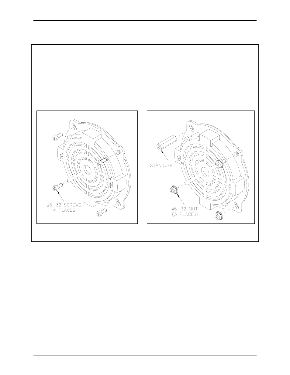
For Wall-Mount Telephones:
For Flush-Mount Telephones
7. Use the #1 Phillips head screwdriver to
remove the screws securing the PCBA to the
standoffs. Save the screws for reassembly.
Move the PCBA aside.
8. Remove and retain the four #6-32 screws
securing the speaker assembly. See Figure 1
below.
Figure 1. For Wall-Mount Telephones
7. Use the #2 Phillips head screwdriver to remove
the screw securing the PCBA to the standoff.
Save the screws for reassembly.
8. Use the ¼-inch nut driver to remove the standoff
and three hex nuts securing the speaker
assembly to the front panel assembly. Save
them for reassembly. See Figure 2 below.
Figure 2. For Flush-Mount Telephones
9. Remove existing gasket from the front panel and scrape away any adhesive residue.
N
OTE
: Remove and discard the piezo speaker.
Installation of New Non-Metallic Piezo Speaker Assembly
1. Place the new speaker assembly on the front panel mounting holes using the previously saved
hardware.
2. Use the enclosed tie wrap to secure the push button and speaker cables together.
3. Secure the PCBA in place with the previously saved Phillips screws and the Phillips screwdriver.
4. Plug the speaker assembly cable in the PCBA.