GAI-Tronics 12562-103 SMART Emergency Phone PCBA Replacement Kit User Manual
Page 2
Pub. 42003-198B
M
ODEL
12562-103
S.M.A.R.T.
E
MERGENCY
T
ELEPHONE
PCBA
R
EPLACEMENT
K
IT
Page:
2 of 4
f:\standard ioms - current release\42003 kit manuals\42003-198b.doc
04/09
3. Disconnect the red and green wires from the telephone line connection on the PCBA. Save the modular
cord.
4. Unscrew the four corner screws from the PCBA. Save the screws.
Installing the New PCBA
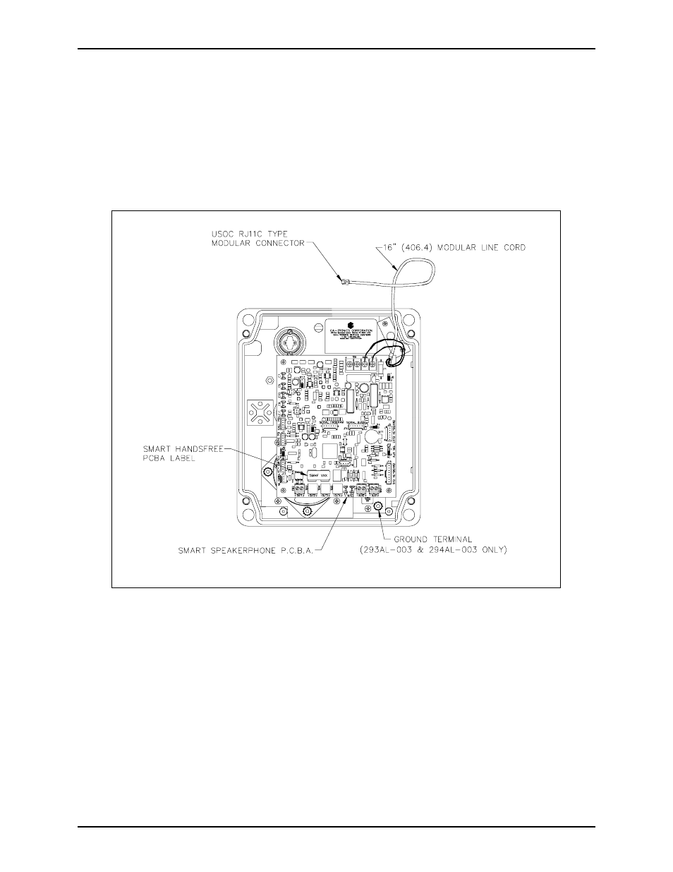
1. Align the holes in the four corners of the new PCBA with the standoffs in the telephone, maintaining
proper orientation. See Figure 1.
Figure 1. PCBA Connections for Model 293-003, 293AL-003, and 294AL-003
2. Use the screws (from step 4 in the previous section) to secure the PCBA.
3. Reconnect the red (ring) and green (tip) telephone wires to the PCBA.
4. Reconnect the microphone, speaker, LED indicator, keypad (Model 294AL-003 only) and switch
cable(s) to the board.
5. Use the Model 233-001 Tamper-Resistant Screwdriver to install the four front panel screws.