GAI-Tronics 12560-101 AC Transformer Shield Kit User Manual
Page 2

Pub. 42003-185A
M
ODEL
12560-101
AC
T
RANSFORMER
S
HIELD
K
IT
Page:
2 of 2
\\s_eng\gtcproddocs\standard ioms - current release\42003 kit manuals\42003-185a.doc
6/00
3. Loosen the four side screws holding the front panel to the rear chassis.
4. Carefully slide and separate the front panel from the rear chassis and lay the panel over to the right
side.
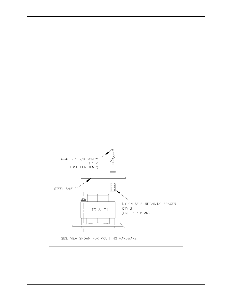
5. Remove the inner two 4-40 screws that secure the T3 and T4 transformers to the 69382-001 PCBA.
(One screw, located closest to the center of PCBA, is removed from each transformer.) Refer to
Figure 1 below.
N
OTE
: Retain the two #4 internal tooth washers.
6. Insert the two spacers that are supplied into the same side of the shield.
7. Place the shield over top of T3 and T4 insuring that the spacers are against the core of the
transformers.
8. Using the retained lock washers and the longer, supplied screws, tighten the shield and T3 and T4
transformers to the PCBA.
9. Carefully mate the front panel to the rear chassis. Insure that all four side-mounted screws are
correctly located in the rear chassis and tighten.
10. Install the unit into enclosure, replace the four mounting screws, and tighten.
11. Apply ac power and check for proper operation.
Figure 1.
- 370-201, 372A Interface Amplifier Assembly (10 pages)
- 13314-001 and 13314-002 Div. 2 Hazardous Area Speaker Assembly using 13314 Driver (3 pages)
- 230-001 Pole-Mounting Kit (3 pages)
- Electro Sound Electro-Sound Communication System (9 pages)
- 13314-004 Div. 2 Hazardous Area 100-Volt Horn Driver (5 pages)
- XGM003A Gooseneck Microphone Kit (5 pages)
- XGM003A Gooseneck Microphone Kit (2 pages)
- XGM003A Gooseneck Microphone Kit (26 pages)
- 9974 Junction Box (5 pages)
- 232-001 Pole Mounting Kit (3 pages)
- 13411-001 and 13411-002 Replacement Voice Coil / Diaphragm Assemblies (5 pages)
- 726-101 Single Party Desktop Subset (4 pages)
- 726-101 Single Party Desktop Subset (5 pages)
- 478-002 Centra-Page Desktop Subset (6 pages)
- 239WM-002 Slim Wall-Mount Stanchions (4 pages)
- 210-001 Corridor Telephone (10 pages)
- 239WM-002 Slim Wall-Mount Stanchions (10 pages)
- 239WM-002 Slim Wall-Mount Stanchions (5 pages)
- 239WM-002 Slim Wall-Mount Stanchions (6 pages)
- 239WM-002 Slim Wall-Mount Stanchions (4 pages)
- Speaker / Horn Installation for GAI-Tronics Communication System (8 pages)
- 700 Series 120 V AC Page/Party Systems (10 pages)
- 700 Series 24 V DC Page/Party Systems (14 pages)
- 703-002 Multi-Party 24 V DC Amplifier Enclosures (13 pages)
- 703A Indoor Multi-Party 115 V AC Amplifier Enclosure (8 pages)
- 703A Indoor Multi-Party 115 V AC Amplifier Enclosure (3 pages)
- 723-001 Remote Handset / Speaker Amplifier (3 pages)
- 723-003 24 V DC Remote Handset/Speaker Amplifier (7 pages)
- 237-001 Plug-in Power Supply for Telephones (3 pages)
- 733-002 Single Party 24 V DC Amplifier Enclosure (13 pages)
- 7855-001 Explosion-proof Handset Stations (13 pages)
- 7855-002 24 V DC Explosion-proof Page/Party Handset Stations (14 pages)
- 670-001 Explosion-proof Page/Party Speaker Station (9 pages)
- 670-002 24 V DC Explosion-proof Page/Party Speaker Station (10 pages)
- 13351 Integral Loudspeakers (5 pages)
- 305-001 Line Balance Assembly (3 pages)
- 272-001 Intrinsically-Safe Telephones (13 pages)
- 713-102 24 V DC Page/Party Remote Speaker Amplifier (5 pages)
- 263-000 Isolation Barrier Unit (I.S. Phone) (14 pages)
- 774-001 Portable Station Enclosure (Page/Party) (5 pages)
- 234SBA 234SBA Stanchion Broadcast Assembly (12 pages)
- 491-204 Mine Dial / Page Phone (10 pages)
- 773-001 Outdoor Jack Station (Page/Party) (3 pages)
- 491 Series Mine Dial / Page Phone Interface Cabinet (23 pages)
- 268-001 Intrinsically-Safe Telephone Rack-Mount System (14 pages)