Installing the new pcba – GAI-Tronics 12702-001, 12702-002 Amp PCBA Kit for EZ Page Intercom User Manual
Page 2
Pub. 42003-179A
M
ODELS
12702-001 and 12702-002
EZ
P
AGE
A
MPLIFIER
PCBA
R
EPLACEMENT
K
IT
Page: 2 of 3
\\s_eng\gtcproddocs\standard ioms - current release\42003 kit manuals\42003-179a.doc
5/99
6. Using the #1 screwdriver, remove the
screw that secures the fuseholder to the
mounting bracket and retain.
7. Carefully pull the front cover assembly
away from the enclosure.
Note the location of the speaker
volume/on-off switch (R1/SW1) and
Listen/Talk switch (SW2) for
reinstallation.
8. Ensure that the speaker volume/on-off
switch (R1/SW1) is turned fully counter
clockwise to the off position.
9. Using the hex allen wrench, loosen the two
screws that secure the knob. Remove
knob and retain.
10. Using the 5/8-inch wrench, remove the
sealing nut holding the Listen/Talk switch
to the front cover and retain.
11. Using the 1/2-inch wrench, remove the
sealing nut holding the speaker volume/on-off switch (R1/SW1) to the front cover and retain. N
OTE
:
This will allow separation of the front cover from the PCBA’s heatsink plate.
12. Carefully remove the speaker volume/on-off switch (R1/SW1) and Listen/Talk switch (SW2) from
the back of the PCBA’s heatsink plate, noting their location and orientation for reinstallation.
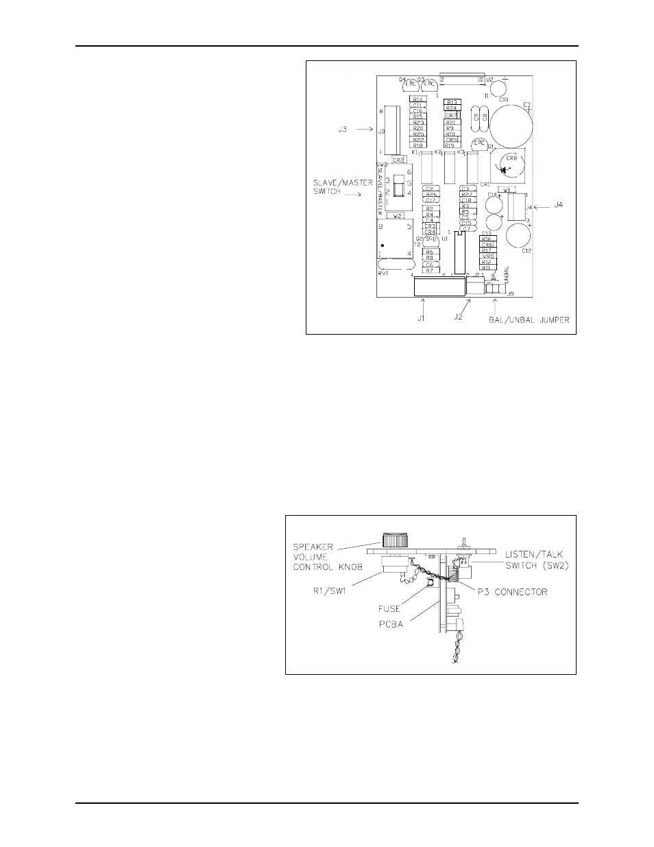
Installing the New PCBA
1. Before installing the new PCBA,
modify the new PCBA’s
S
LAVE
/M
ASTER
switch and the
B
AL
/U
NBAL
jumper settings to match
the old PCBA’s settings, if necessary.
Refer to Figure 1.
2. Place the new PCBA’s heatsink plate
and front cover together.
3. Reinstall the speaker volume/on-off
switch (R1/SW1) through the
heatsink plate and through the front
cover. Ensure that the associated
anti-rotation pin is properly inserted into the locking notch and the attached wires are positioned
towards the fuse holder location. Refer to Figure 2.
4. Push the small panel sealing nut over the speaker volume/on-off switch’s shaft and lightly tighten
against the front cover.
Figure 1. PCBA switch/jumper location
(Factory settings shown)
Figure 2. Outline Diagram