GAI-Tronics 12520-006, 12520-007 Push Button Replacement Kit for 293, 294, 297, 298 Series Emergency Phones User Manual
Page 2
Pub. 42003-173
M
ODELS
12520-006
AND
12520-007
R
OUND
P
USH
-B
UTTON
A
SSEMBLY
R
EPLACEMENT
K
IT
Page:
2 of 3
\\s_eng\gtcproddocs\standard ioms - current release\42003 kit manuals\42003-173.doc
11/98
4. Use the wire cutters to snip the tie
wrap that is securing the push-
button assembly cable to the other
wires.
5. Unplug the push-button assembly
cable connector from the PCBA.
Be sure to note the location of the
connection for re-assembly.
6. For Model 293AL and 294AL:
Place the front cover assembly
face down on a flat surface.
For Model 293: Pull the front
cover assembly straight out and
away from the back box. Place
the front cover assembly face down on a flat surface.
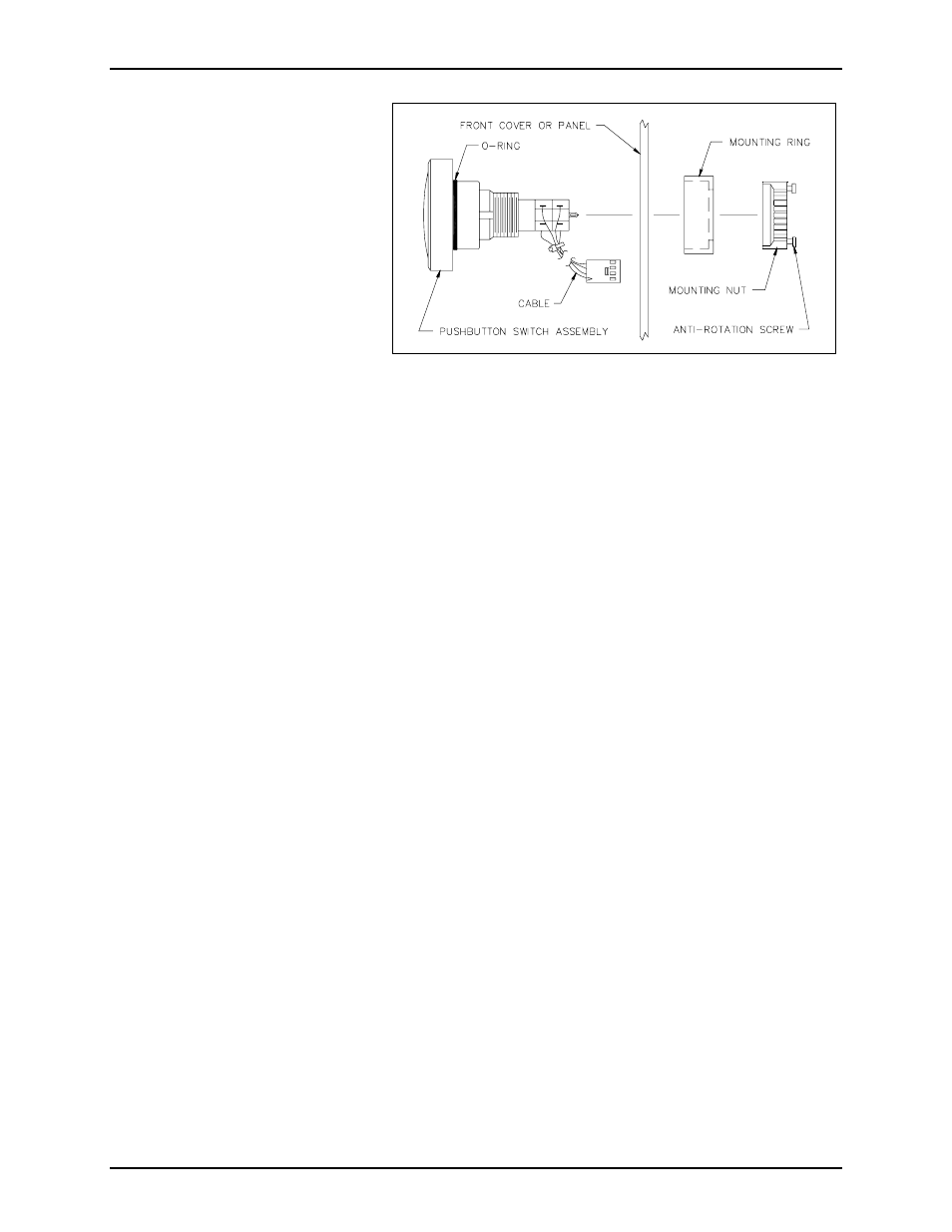
7. Using the 1/8-inch straight slot screwdriver, loosen the anti-rotation screws on the mounting nut.
See Figure 1.
8. Remove and discard the push-button assembly, the mounting nut, and the mounting ring.
Installing the New Push-Button Assembly
1. From the front side of the panel, push the new push-button assembly through the hole. See Figure 1.
2. Secure the push-button assembly to the front cover using the mounting ring and the mounting nut. See
Figure 1.
N
OTE
: Ensure that the o-ring seal is in its proper location, as shown in Figure 1.
3. Tighten the anti-rotation screws on the mounting nut.
4. Model 293 only: Align the hinge plugs with the rear enclosure and push firmly into place.
5. Plug the push-button assembly cable into the PCBA at the proper location noted earlier.
6. Use the enclosed tie wrap to secure the push-button assembly cable to the other wires.
7. Reconnect the telephone line cord.
8. Model 293 only: Swing the front cover closed.
9. Align the front cover with the rear enclosure, and use the Model 233 Tamper-Resistant Screwdriver to
secure four front cover screws (previously saved).
Figure 1. Push-Button Switch Assembly,
Exploded View