Installation as a wall receptacle – GAI-Tronics 12587-001 Subset Extension Cable User Manual
Page 2
Pub. 42003-111A
M
ODEL
12587-001
S
UBSET
E
XTENSION
C
ABLE
A
SSEMBLY
R
EPLACEMENT
K
IT
Page
2 of 4
f:\standard ioms - current release\42003 kit manuals\42003-111a.doc
10/12
Installation as a Wall Receptacle
1. Arrange the cable so that P1 is located at the amplifier enclosure, and the blunt end of the cable is
located at the wall receptacle. After all connections are made, P1 will plug into the receptacle at the
amplifier enclosure, and the blunt end of the cable will connect to the wall receptacle.
2. Install the 50-foot cable/plug assembly in the wall from the amplifier location to the desired wall
receptacle location in a nominal 2
3 1.5 inches minimum depth single gang electrical box. Check
the appropriate electrical code.
3. Cut the cable to the desired length, allowing adequate cable for the installation of the wall plate.
4. From the blunt end of the cable, strip 1.75 inches off from the cable jacket, and strip 0.25 inch off
from the insulation on the 24 individual wires. The cable contains one shielded pair of wires with a
drain wire. Trim the shield until it is even with the cable jacket. Twist the drain wire, and cover it
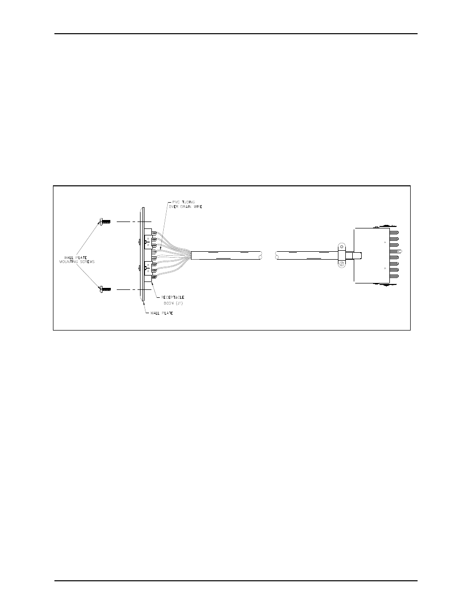
with the 1.5-inch PVC tubing (supplied) prior to soldering it to terminal 14 of receptacle J1.
5. See Figure 4 for proper wire color terminations. Solder all wire leads and drain wire to receptacle J1
on the wall plate as indicated in Figure 2. Make sure that there are no wire strands touching any
other terminations.
6. Install the wall plate using the two mounting screws provided.
7. Plug P1 into the amplifier enclosure and the subset plug into the wall receptacle J1. Be sure that the
connector housing latching tabs are properly in place.
Figure 1. Installation as a Wall Receptacle