Available adjustments, Front cover reattachment – GAI-Tronics ICS Page/Party Remote Subset Handset/Speaker Amplifier Station User Manual
Page 2
Pub. 42004-725L2HQG
ICS Class I, Div. 2 Page/Party
®
Station Quick Installation Guide
Page 2 of 2
f:\standard ioms - current release\42004-xxxxqg quick guides\42004-725l2hqg.doc
03/15
Available Adjustments
Most optional equipment is preconfigured to a default standard at the factory. The
following is a partial list of the available adjustments and settings that may be
needed:
Main PCBA
VLC Option
SmartSeries Option
Speaker Volume
Speaker Volume
FSK Transmit Level
Receiver Volume
VLC Override
Address
Transmit Level
Test Tone
Mutual Muting
Page Control
Termination PCBA
Remote Signaling
Speaker impedance
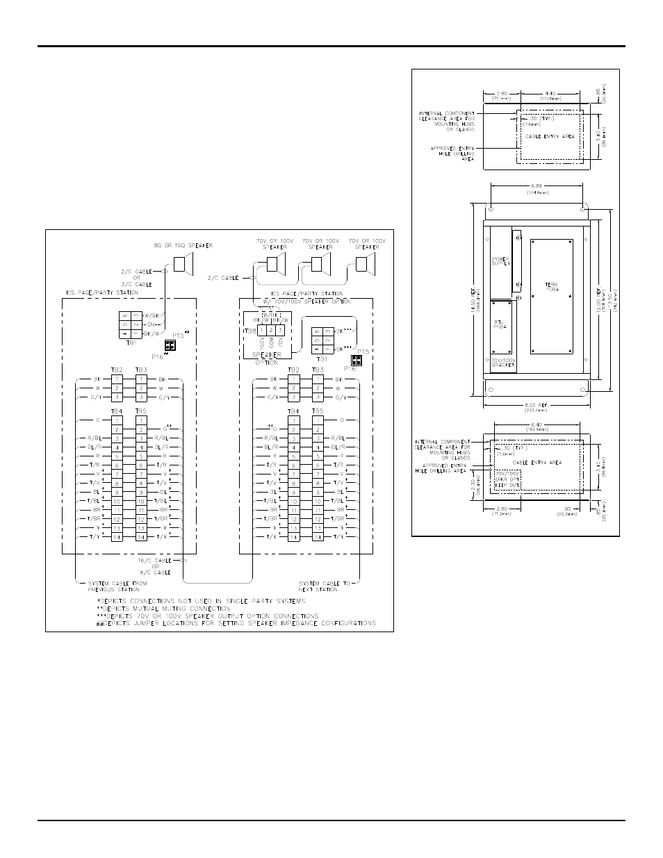
Figure 3. Typical installation wiring configuration
N
OTE
: Station input power can be through system cable or through a separate power source cable.
See Pub. 42004-725L2 for the possible beacon, RTU activation, and speaker impedance configurations.
Front Cover Reattachment
Connect any cable harnesses that were disconnected during mounting. Place the front cover on the rear enclosure, being careful not to pinch
any cables. Attach the front cover with the four screws and washers provided. Torque the screws to 10–12 in-lbs (1.13–1.36 n-m).
NEMA 12
NRTL Listed for USA and Canada
...................................................................................................
Class I, Groups A, B, C, and D, Division 2;
Class II, Groups F and G, Division 2;
Class III, Division 2 Hazardous Locations
Temperature code, T4A - USA
T3C - Canada
Figure 2. Suggested wire entry locations