Installation, Operation – GAI-Tronics 13118-009 TVP Barrier Assembly User Manual
Page 3
Pub.: 42004-678L2A
Model 13118-009 TVP Barrier Assembly
Page: 3 of 4
\\s_eng\gtcproddocs\standard ioms - current release\42004 instr. manuals\42004-678l2a.doc
10/02
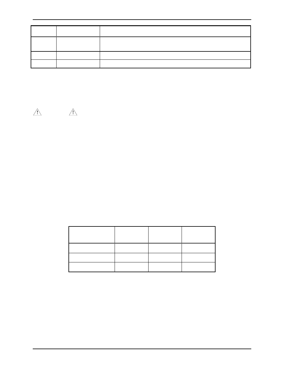
Pin No. Function
Remarks
16
CLS-
This terminal is used with CLS+ when dry contact All-Call control is
employed at field stations via a separate pair of wires.
17 EGND
Earth
ground
18 EGND
Earth
ground
N
OTE
: Terminal Blocks JTB2 and JTB3 are for internal cabinet wiring only. Do not connect any field
cables to either of these terminal blocks.
Installation
CAUTION
Safety Note: If GAI-Tronics Page/Party
®
cable is used, ensure the ac power conductors are disconnected
from any power source during the installation.
1. Snap the Modular TVP Barrier assembly onto one of the vertical DIN mounting rails located in the
rear of the cabinet.
2. Connect the appropriate Page/Party
®
cable to modular terminal block JTB1 per table 1 using the
mating plug provided.
3. Attach the appropriate ribbon cable to the DB-25 connector (J1).
4. Attach a ground wire to JTB1-17 or JTB1-18.
5. If this module is replacing a damaged module, re-connect (plug-in) any pre-wired harnesses to/from
other modules at JTB2 and JTB3.
6. Check and/or set positioning of the party line jumper clips J2 through J7 per the following chart:
Jumper Clip
Pair
Party Line Position 1 Position 2
J2/J3 3
Connected
Isolated
J4/J5 4
Connected
Isolated
J6/J7 5
Connected
Isolated
*N
OTE
: All jumper clips are factory set to position 1. Setting any jumper clip pair to the “Isolated”
position automatically applies 33-ohm line balancing to the designated line.
Operation
None.
Software Configuration
None.