GAI-Tronics 69268-001 Amplifier Zone Interface II (AZI) User Manual
Page 5
Pub. 42004-614L2C
69268-001 Amplifier Zone Interface II PCBA
Page: 5 of 9
f:\standard ioms - current release\42004 instr. manuals\42004-614l2c.doc
11/10
8. Apply power to the card rack assembly. You can expect to see the following responses on the AZI II
board:
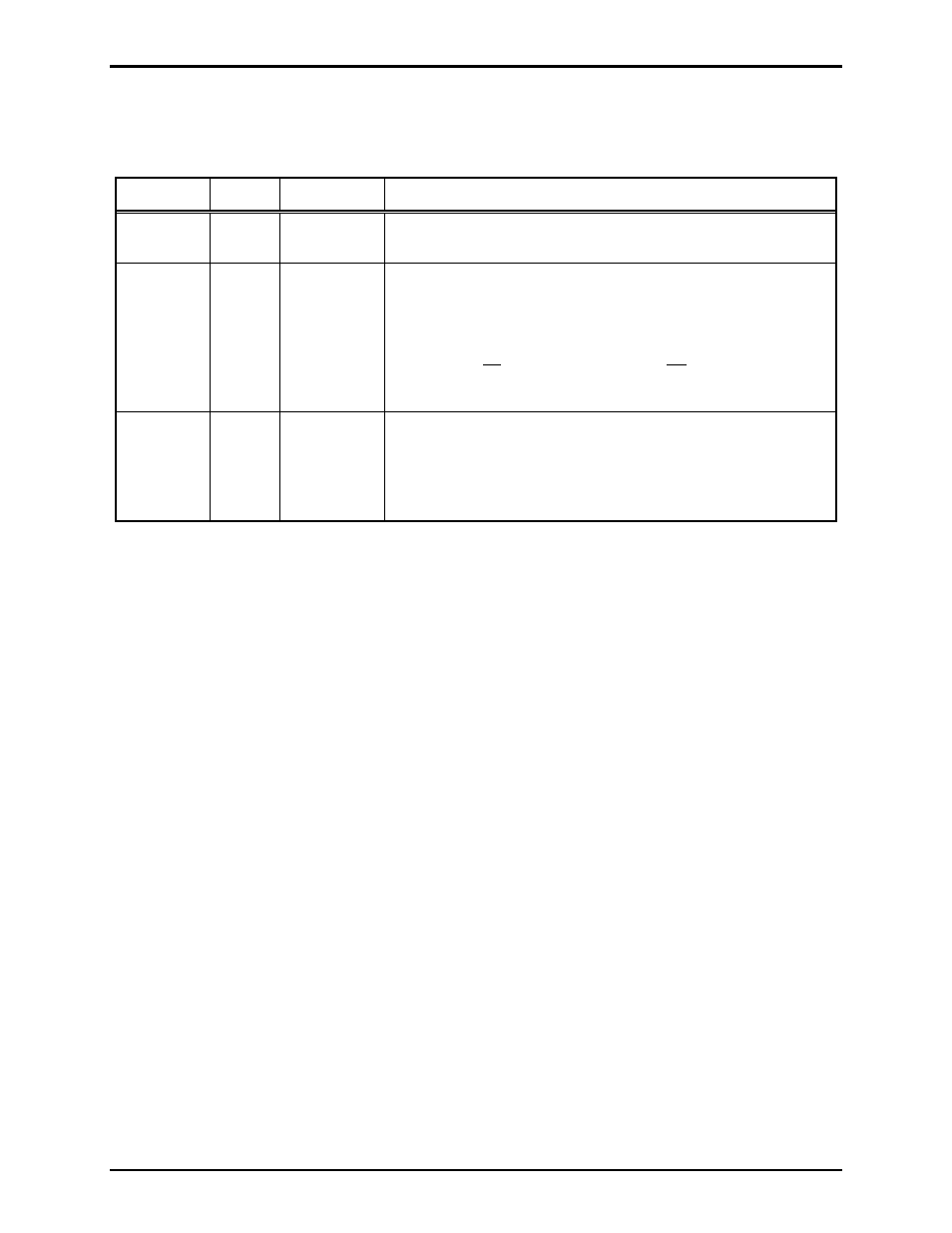
These responses are summarized in the table below:
LED Color
LED
State
Condition
ON-LINE
Green
On/Off
After a brief delay, the ON-LINE LED illuminates.
On indicates AZI II board is powered and recognized by MCU.
RTS
Yellow Flashes
The
RTS
LED begins flashing continuously if external
modules are configured to communicate with the AZI II board.
Flashing indicates that the AZI II board is transmitting data via
RS485.
(The LED is on when transmitting, and off when not
transmitting. The rapid switching between these two
conditions results in flashing.)
EOL
F
AULT
Red On/Off The
EOL
FAULT
LED does NOT illuminate if all the end-of-
line (EOL) external modules are responding to the AZI II
Board.
ON indicates an EOL device is not responding. LED is
extinguished when all EOL devices respond to MCU.
9. Verify the AZI II Board properly routes audio and communicates with the external devices as
indicated in the system manual.
10. Adjust the normal level during a period when audio is routed via the AZI II board and normal
volume level is selected by the MCU. The volume control labeled NORMAL
LEVEL
is located on
the AZI II front bezel. Rotate clockwise to increase the normal level.
11. Adjust the emergency level during a period when audio is routed via the AZI II board and emergency
level is selected by the MCU. The volume control labeled EMERGENCY
LEVEL
is located on the
AZI II front bezel. Rotate clockwise to increase the emergency volume.
12. Specific audio levels for the Amplifier 6 output and the Amplifier 12 output can be set independently
from the remaining ten amplifiers. If they are used, adjust the audio output levels of Amplifier 6 and
Amplifier 12 while audio is routed via the AZI II board. There are two user adjustments labeled as
AMP 6
VOL
and AMP 12
VOL
on the AZI II board. Rotate the corresponding volume control
clockwise to increase volume.
13. Specific audio level for the supervisory tone can be adjusted for all amplifiers simultaneously. R157
can be used to raise or lower the supervisory tone level. Rotating the pot clockwise will increase the
level.
14. The start-up and check-out are now complete.