Installation, Mounting, Wiring – GAI-Tronics 378-002 Monitored Input Module (MIM) Station User Manual
Page 3: Power
Pub. 42004-490A
Model 378-002 Monitored Input Module Station
Page 3 of 10
f:\standard ioms - current release\42004 instr. manuals\42004-490a.doc
03/14
Installation
CAUTION
Do not install this equipment in hazardous areas. Disconnect power before installing or removing
the MIM.
Mounting
The Model 378-002 MIM Station enclosure is not supplied with conduit or cable gland holes since cable
quantity, size, and entry location vary with each installation.
Drill or punch openings at the required locations before mounting the enclosure. Typically, multiple
cables entries are required for power, serial data line, and input wiring. Refer to the “Wiring” section
below. Use caution when drilling or punching the enclosure to avoid damaging the internal components.
Bottom cable entry is recommended to prevent moisture from entering the enclosure and dripping onto
the terminals or circuit boards.
Mount the enclosure to a suitable surface using appropriate customer-supplied hardware. Refer to Figure
1 for mounting hole dimensions.
Remove the shipping tie-wrap that is securing the PCBA to its mounting Snaptrack.
Wiring
The MIM Station requires 120 V ac power and a serial data line connection (RS-485) to the ADVANCE
system control cabinet. Up to eight activation switches (inputs) are connected as needed. Each
connection is explained below.
Power
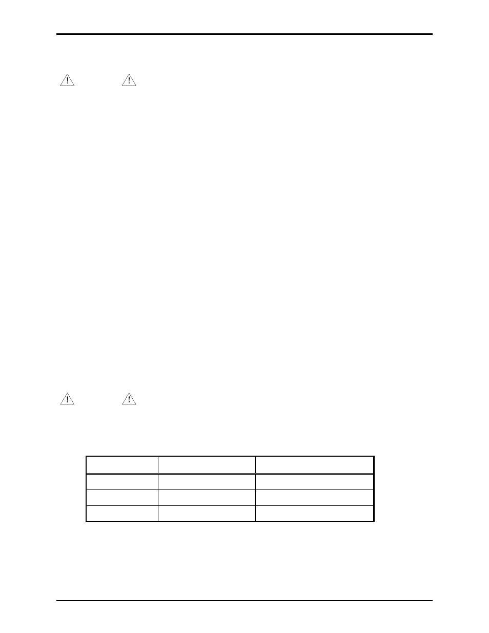
120 V ac power is connected to terminal block TB13 at the top of the panel. Refer to Figure 1.
WARNING
Insure proper grounding to protective earthing.
Earth grounding provisions are provided.
Table 1.
Function Terminal
Block Wire
Color
AC Line (hot)
TB13-1
Black
Neutral TB13-2 White
Ground TB13-3
Green/yellow