Recommended cabling, Voip telephone input contacts, Voip telephone output contacts – GAI-Tronics 393-700 RED ALERT 300 Series Hands-free VoIP Telephone Manual User Manual
Page 19: Status indication, Power, Heartbeat, Eact
P
UB
.
42004-441G
H
ANDS
-
FREE
V
O
IP
T
ELEPHONES
P
AGE
17 of 24
e:\standard ioms - current release\42004 instr. manuals\42004-441g.doc
02/15
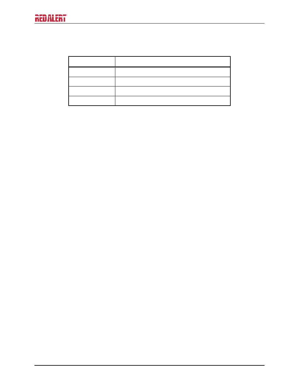
Recommended Cabling
Table 5. Recommended Cabling
Cable Use
Size and Type
Power
Two-conductor, No. 22 AWG is typical
Inputs
Two-conductor, No. 22 AWG is typical
Output contacts
Two-conductor, No. 18 AWG is typical
Antenna RG58
coaxial
cable
VoIP Telephone Input Contacts
Each RED ALERT
®
VoIP Telephone accepts four inputs. Refer to the “Specifications” section of this
manual for the input ratings.
The function of each input is configurable. Inputs can be configured for one of the following modes: On,
Off, or On/Off. The signals can also be inverted between active high (INVERT) or active low
(NORMAL). Activation of these inputs can be configured to update a SYSLOG or generate an email.
Please refer to Figure 16 on page 15 of this manual and the “Logic Settings” section of GTC Pub. 42004-
396, “VoIP Telephone Configuration Guide” for programming instructions for these inputs.
VoIP Telephone Output Contacts
Each RED ALERT
®
VoIP Telephone contains two volt-free output contacts. Refer to the
“Specifications” section of this manual for the output ratings. Both outputs are single-pole, single-throw
contacts.
The function of each output is configurable. Outputs can be configured for one of the following modes:
On, Off, Pulse, Mute, Ring, Call, Connect, Hook, In Use, Ring Cadence, Ring Out, Page, Registered, or
Emergency. In some modes, the duration of the activation or on/off times can also be set. Please refer to
Figure 16 on page 15 of this manual and the “Logic Settings” section of GTC Pub. 42004-396, “VoIP
Telephone Configuration Guide” for programming instructions for these outputs.
Status Indication
Power
The Power LED located on the VoIP PCBA illuminates when power is applied to the telephone. Refer to
Figure 16 on page 15 for location.
Heartbeat
The Heartbeat LED located on the VoIP PCBA will flash once communication over the LAN is
established. Refer to Figure 16 on page 15 for location.
EACT
The EACT LED located on the VoIP PCBA will turn ON when VoIP PCBA is connected to an Ethernet
device and flash when data is being transmitted. Refer to Figure 16 on page 15 for location.
- 393AL-700 RED ALERT 300 Series Hands-free VoIP Telephone Manual 397-700 RED ALERT 300 Series Hands-free VoIP Telephone Manual 398-701 RED ALERT 300 Series Hands-free VoIP Telephone Manual 394AL-702 RED ALERT 300 Series Hands-free VoIP Telephone Manual 397-701 RED ALERT 300 Series Hands-free VoIP Telephone Manual 398-702 RED ALERT 300 Series Hands-free VoIP Telephone Manual