Specifications – GAI-Tronics 12599-001 Hot Standby Amplifier Module User Manual
Page 11
Pub. 42004-375A
Model 12599-001 Hot Standby Amplifier Module
Page: 11 of 11
\\s_eng\gtcproddocs\standard ioms - current release\42004 instr. manuals\42004-375a.doc
09/05
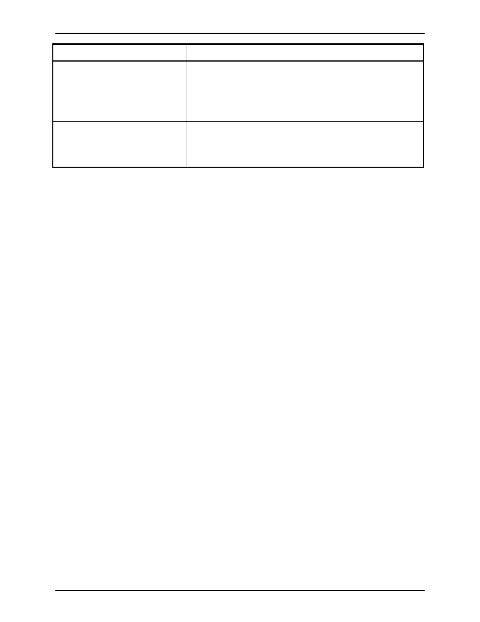
Problem Solution
Amplifiers on the second
(cascaded) module operate
independent of the priority control
scheme described on page 8.
In a cascade arrangement, switch S1 must be set to the 1ST
position at the first module, and the 2ND+ position at the second
module, and all subsequent modules, as described on page 9.
Also, be sure wiring at the IN/OUT
CNTL terminals at TB26
conforms to Figure 5 or Figure 6 on pages 4 or 5, respectively.
After performing all wiring checks,
trouble-shooting, etc. as described
in this section, the module still does
not function properly.
Contact GAI-Tronics service for repair or replacement of the
module in accordance with the information provided on page 10.
Specifications
Electrical
Power requirements ............................................................................... 9.5 to 14 V dc (12 V dc nominal)
Current draw .............................................................................................. 300 mA maximum @ 12 V dc
Number of amplifier inputs.................................................................. 6-single channel or 3-dual channel
Fault input terminal voltage ........................................................................................... 6 V dc (nominal)
Fault input trigger voltages ........................................................... 6.01 V dc (active); 5.99 V dc (inactive)
Fault input circuit current ..............................................................................................................1.2 mA
Number of fault output contacts.................................... 6 (single channel mode) or 3 (dual-channel mode)
Fault output contact type ................................................................................................. Single form “C”
Fault output contact rating ................................................................................. 2 A maximum @ 30 V dc
Amplifier Audio Switching
Amplifier type ........................................................................................................ Single or dual-channel
Audio input levels (typical per circuit) .................................. 600 ohm @ .775 Vrms (0 dBm) to 1.5 Vrms
Amplifier output power (maximum per circuit)............................................. 720 watts (100% duty cycle)
Speaker load switching.................................................................................. Standard 4, 8 or 16-ohms, or
25 V, 70 V or 100 V constant voltage lines
Terminations
Type..................................................................................................... Modular (plug-in) terminal blocks
Minimum conductor size ............................................................................................ 28 AWG (0.5 mm
2
)
Maximum conductor size............................................................................................ 12 AWG (3.0 mm
2
)
Mechanical
Module dimensions .................................... 12.00 L
× 4.00 W × 1.25 H inches (304.8 × 101.6 × 31.7 mm)
Module weight ................................................................................................................. 1.1 lbs. (0.5 kg)
Environmental
Temperature range (operating/storage)............................................................. 32
° to 140° F (0° to 60° C)
Humidity....................................................................................... 85% non-condensing relative humidity