GAI-Tronics 1931888-3011 Page/Party to Coupler User Manual
Page 8
Pub. 42004-245B
Model 1931888-3011 Page/Party
®
to Radio Coupler
Page:
8 of 10
\\s_eng\gtcproddocs\standard ioms - current release\42004 instr. manuals\42004-245b.doc
03/08
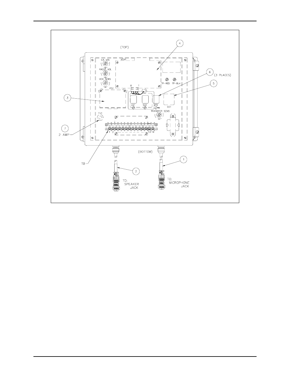
Figure 5. Part Location Diagram
Typical audio signal levels within coupler from Page/Party
®
station to coupler:
With approximately 1.5 Vrms on Page/Party
®
system party line (TB-7 and 8); with an associated
Page/Party
®
station off-hook:
Audio signal at TB-12 (com) and 13; Mic In = approximately 0.45 Vrms, nominal
(Radio Vol. Min/Max range = 0 V/1.24 Vrms)
Typical audio signal levels from coupler to Page/Party
®
station:
• With approximately 10 Vrms of received speaker audio at TB-9 and 10; with XFR relay’s LED 3
NOT illuminated and all associated Page/Party
®
stations on-hook:
Audio signal at TB-3 and 4 (page line) = 0.5 Vrms** nominal.
(UA Vol. Min/Max range = 0 V/3.0 Vrms**)
• With approximately 10 Vrms of received speaker audio at TB 9 and 10; with XFR relay’s LED 3
illuminated and an associated Page/Party
®
station off-hook:
Audio signal at TB-7 and 8 (party line) = 0.5 Vrms** nominal.
(UA Vol. Min/Max range = 0 V/3.0 Vrms**)
**Voltages indicated are typical with indicated signal levels, actual voltages measured may vary with
different audio drive levels.