Specifications, Replacement parts – GAI-Tronics 670-002 24 V DC Explosion-proof Page/Party Speaker Station User Manual
Page 7
Pub. 42004-162E
Model 670-002 24 V DC Explosion-proof Speaker Station
Page 7 of 9
f:\standard ioms - current release\42004 instr. manuals\42004-162e.doc
08/13
Specifications
Power input ......................................................... 21–29 V dc; 1.2 A (optional negative ground or floating)
Dimensions ............................................................. 13.1 H
7.9 W 5.6 D inches; (332 200 143 mm)
Temperature range ............................................................................ −22° F to +158° F (−30° C to +70° C)
Shipping weight .................................................................................................................... 27 lbs. (12.2 kg)
Speaker Amplifier
Output ....................................................................... @ 25 V dc: 12 watts minimum into 8- or 16-ohm load
Voltage gain ........................................................................................................ 20 dB minimum, adjustable
Frequency response ............................................................................. 250–4,000 Hz, +0/−3 dB ref @ 1 kHz
Distortion ............................................................................................ 1% maximum THD @ 1 kHz/12 watt
Input impedance .......................................................................................... 50,000 ohm, minimum @ 1 kHz
Controls ................................................................................................................................. Speaker volume
Explosion-proof Enclosure
Material/finish ...................................................................................................... No. 359.2 Aluminum alloy
Mounting ...................................................................... Wall or column, four 3/8-inch slotted mounting feet
Connections................................................................................. Internal screw-type barrier terminal blocks
Conduit entries ...................................................................................................... Standard top: ¾-inch NPT
Standard bottom: 1.5-inches NPT
Optional bottom: 2-inch NPT
Approvals
NRTL certified for use in US and Canada for the following locations: ...... Class I, Div. 1, Groups C and D
Class II, Div. 1, Groups E, F, and G
Class III, Div. 1
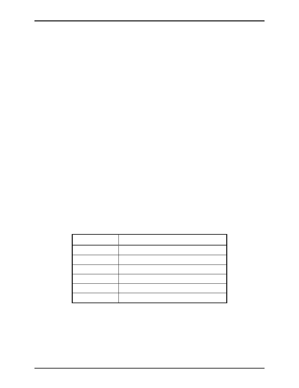
REPLACEMENT PARTS
Part No.
Description
12604-004
Fuse, 2-amp (pack of 10)
61514-005
Harness
Assembly
12542-001
Replacement Front Cover Bolts (pack of 14)
69488-106
PCBA, Handset/Speaker Amplifier
69489-002
PCBA,
Termination
12571-001
Maintenance
Cover
Kit