Step 3 — mounting of line balance assembly – GAI-Tronics 700 Series 24 V DC Page/Party Systems User Manual
Page 6
Pub. 42004-140E
Installation of GAI-Tronics 700 Series 24 V DC Page/Party
®
Systems
Page 6 of 13
f:\standard ioms - current release\42004 instr. manuals\42004-140e.doc
08/13
Step 3 — Mounting of Line Balance Assembly
Each GAI-Tronics Page/Party
®
system requires one line balance assembly. Its function is to properly
load the page and party line circuits. When using GAI-Tronics standard cable select a location that is:
near the electrical center of the system
adjacent to an indoor station in a relatively quiet area
For larger systems, or when using other types of cable, contact a GAI-Tronics representative for further
information. The line balance assembly has one electrical adjustment that must be made while using a
station. See Step 6. The following is the preferred method for mounting the line balance assembly is as
follows:
1. Suspend the assembly from the lower side of the indoor wall station using a 1-inch conduit nipple
(not supplied).
2. Connect one twisted pair wire for the page circuit and another for each of the party lines between the
terminal blocks of the line balance assembly and the associated indoor wall station.
3. Make the wiring connections between the 305 Series Line Balance Assembly and the station
enclosures in accordance with the wiring diagrams at the end of this publication.
Step 4 — Installation of Inter-station Conduit and Cable
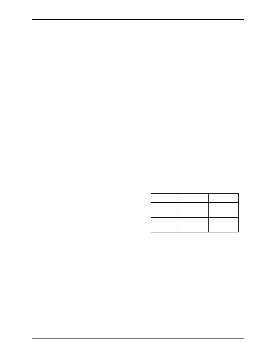
Inter-station cables are generally installed in cable trays or conduit. To assist in determining the conduit
sizes required, the outside diameters of the GAI-Tronics cables discussed in this publication are listed in
the following table. Size and installation of conduit and cable must meet the requirements of applicable
electrical codes.
A ground conductor, with green/yellow insulation,
should be included with cable in any area where no
conduit or non-metallic conduit is used. Non-metallic
enclosures used with metallic conduit and cable without
a ground conductor require a bond between the
conduit(s) and the ground terminal (point 3) within the
enclosure.
Where GAI-Tronics cable is installed, each conductor should be lugged and attached to the terminal-
either in accordance with the color code shown on the applicable accompanying diagram, or in
accordance with special drawings provided for this purpose.
Exception: Some cables have an orange “spare” conductor. Unless otherwise instructed, this
should be insulated and not connected to the terminal strip(s) in the enclosures.
GAI-Tronics cable is considered to be a Class 1 cable (maximum voltage is less than 600 V). In a cable
tray, Class 1 cable may only be grouped with other Class 1 cables. Long runs of GAI-Tronics cable in
proximity to 600-volt cable may cause an undesirable amount of hum being induced onto the Page/Party
®
system’s signaling lines. To reduce undesired hum, it is recommended that runs of cable over ½ mile be
separated from 600-volt cable by a minimum of 12 inches.
Cable Conductors O.D.
60038-101 8 0.60
inches
(15.1 mm)
60029-101 16 0.68
inches
(17.2 mm)