GAI-Tronics Speaker / Horn Installation for GAI-Tronics Communication System User Manual
Page 5
Pub. 42004-135H
Speaker/Horn Installation for GAI-Tronics Communications Systems
Page 5 of 8
f:\standard ioms - current release\42004 instr. manuals\42004-135h.doc
03/15
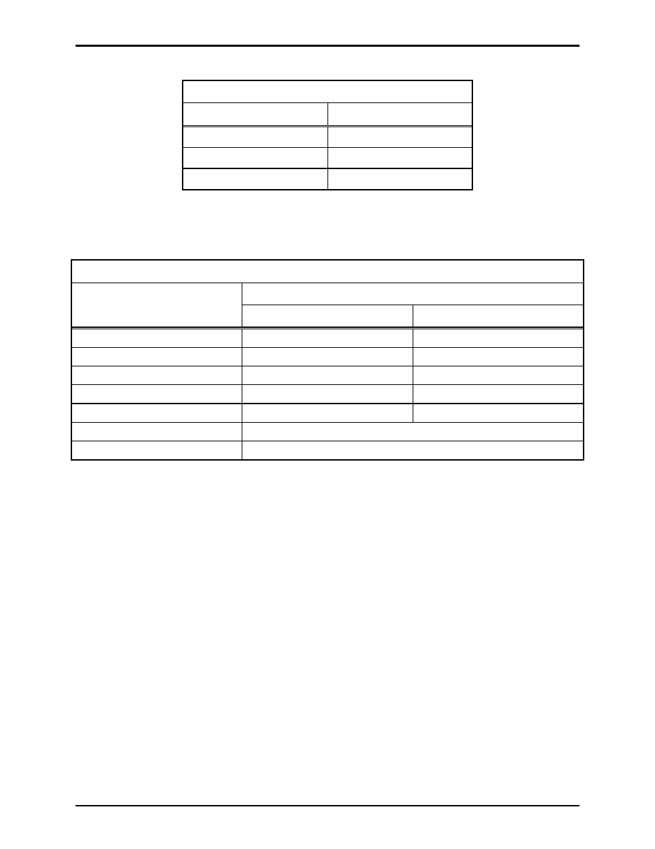
Table 1.
Typical Central Amplifier @ 20% Loss
Wire size
70.7 V Line
No. 18 AWG (0.82 mm
2
)
6250 feet (1903 m)
No. 16 AWG (1.31 mm
2
)
9900 feet (3017 m)
No. 14 AWG (2.08 mm
2
)
15,800 feet (4816 m)
Table 2.
Mounting Assembly Application Chart
Speaker
Drivers
Speaker Horns
13310 (Note 1)
13314
13302-002 415A
411A
13304-002 415A
411A
13305-101 413A
413A
13306-101 (See Note 2)
415A
411A
13340 415A
411A
HP15-8
Has integral driver—use 412B
13328-001
Has integral driver—use 412-002
N
OTES
:
1. When using any Division 1 speaker or driver unit, the speaker mounting assembly may be used only
to support and orient the speaker. Division 1 fittings must be used for electrical connections.
2. When mounting the GAI-Tronics part # 13306-101 speaker horn in an upright orientation, the 411A
mounting assembly can be used with either the 13310 or 13314 Driver. See Figure 5.
- 370-201, 372A Interface Amplifier Assembly (10 pages)
- 13314-001 and 13314-002 Div. 2 Hazardous Area Speaker Assembly using 13314 Driver (3 pages)
- 230-001 Pole-Mounting Kit (3 pages)
- Electro Sound Electro-Sound Communication System (9 pages)
- 13314-004 Div. 2 Hazardous Area 100-Volt Horn Driver (5 pages)
- XGM003A Gooseneck Microphone Kit (2 pages)
- XGM003A Gooseneck Microphone Kit (26 pages)
- XGM003A Gooseneck Microphone Kit (5 pages)
- 9974 Junction Box (5 pages)
- 232-001 Pole Mounting Kit (3 pages)
- 13411-001 and 13411-002 Replacement Voice Coil / Diaphragm Assemblies (5 pages)
- 726-101 Single Party Desktop Subset (5 pages)
- 726-101 Single Party Desktop Subset (4 pages)
- 478-002 Centra-Page Desktop Subset (6 pages)
- 239WM-002 Slim Wall-Mount Stanchions (5 pages)
- 239WM-002 Slim Wall-Mount Stanchions (6 pages)
- 239WM-002 Slim Wall-Mount Stanchions (4 pages)
- 239WM-002 Slim Wall-Mount Stanchions (4 pages)
- 210-001 Corridor Telephone (10 pages)
- 239WM-002 Slim Wall-Mount Stanchions (10 pages)
- 700 Series 120 V AC Page/Party Systems (10 pages)
- 700 Series 24 V DC Page/Party Systems (14 pages)
- 703-002 Multi-Party 24 V DC Amplifier Enclosures (13 pages)
- 703A Indoor Multi-Party 115 V AC Amplifier Enclosure (8 pages)
- 703A Indoor Multi-Party 115 V AC Amplifier Enclosure (3 pages)
- 723-003 24 V DC Remote Handset/Speaker Amplifier (7 pages)
- 723-001 Remote Handset / Speaker Amplifier (3 pages)
- 237-001 Plug-in Power Supply for Telephones (3 pages)
- 733-002 Single Party 24 V DC Amplifier Enclosure (13 pages)
- 7855-001 Explosion-proof Handset Stations (13 pages)
- 7855-002 24 V DC Explosion-proof Page/Party Handset Stations (14 pages)
- 670-001 Explosion-proof Page/Party Speaker Station (9 pages)
- 670-002 24 V DC Explosion-proof Page/Party Speaker Station (10 pages)
- 13351 Integral Loudspeakers (5 pages)
- 305-001 Line Balance Assembly (3 pages)
- 272-001 Intrinsically-Safe Telephones (13 pages)
- 713-102 24 V DC Page/Party Remote Speaker Amplifier (5 pages)
- 263-000 Isolation Barrier Unit (I.S. Phone) (14 pages)
- 774-001 Portable Station Enclosure (Page/Party) (5 pages)
- 234SBA 234SBA Stanchion Broadcast Assembly (12 pages)
- 491-204 Mine Dial / Page Phone (10 pages)
- 773-001 Outdoor Jack Station (Page/Party) (3 pages)
- 491 Series Mine Dial / Page Phone Interface Cabinet (23 pages)
- 268-001 Intrinsically-Safe Telephone Rack-Mount System (14 pages)