Foxconn 661FX7MI-RS User Manual
Page 11
Chapter 1 Product Introduction
4
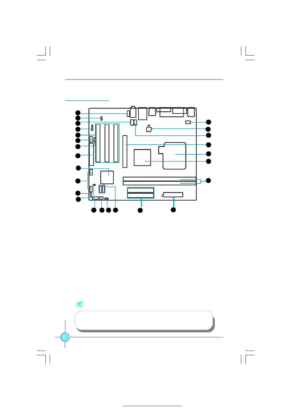
Motherboard Layout
Note:
The above motherboard layout is provided for reference only;
please refer to the physical motherboard.
1. Front Audio Connector
2. BIOS TBL_EN Connector
3. CD_IN Connector
4. IrDA Header
5. PCI Slots
6. COM2 Connector
7. S/PDIF OUT Connector
8. FDD Connector
9. South Bridge: SiS 964/964L
10. Front USB Headers
11. Speaker Connector(optional)
12. Chassis Intruder Connector
13. Front Panel Connector
14. System Fan Connector
15. Clear CMOS Jumper
16. SATA Connector(optional)
17. HDD Connector
18. 20-pin ATX Power Connector
19. Memory Slots
20. North Bridge: SiS 661FX/661GX/648FX/648C
21. CPU Socket
22. AGP 8X Slot
23. AUX_IN Connector(optional)
24. 4-pin ATX 12V Power Connector
25.CPU FAN Connector
1
2
3
4
5
6
7
8
9
10
11
12
13 14 15 16
17
18
19
20
21
22
23
24
25
PDF 文件使用 "pdfFactory" 试用版本创建