Chapter 2 installation instructions – Foxconn 865M01-G-6ELS User Manual
Page 33
Chapter 2 Installation Instructions
25
865M01G/PE/GV User Manual
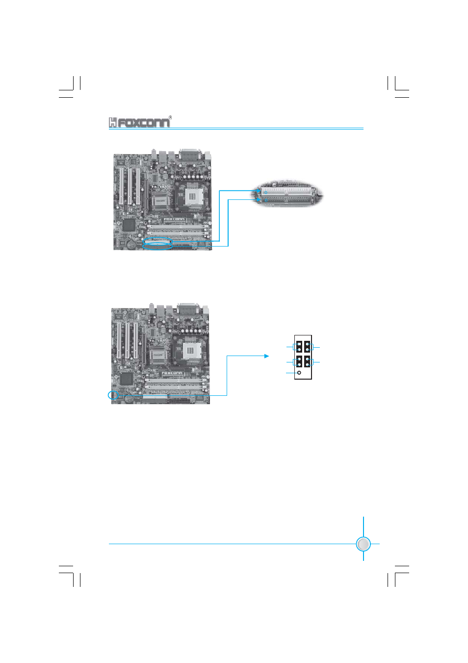
PIDE
SIDE
Front Panel Connector: CN35
This motherboard includes one connector for connecting the front panel switch
and LED indicators.
CN35
Hard Disk LED Connector (HD-LED)
The connector connects to the case’s HDD indicator LED indicating the activity sta-
tus of IDE and SATA HDD hard disk.
Reset Switch (RESET)
Attach the connector to the Reset switch on the front panel of the case; the system
will restart when the switch is pressed.
Power LED Connector (PWR LED)
Attach the connector to the power LED on the front panel of the case. The Power
LED indicates the power supply status. When the system is in S0 status, the LED is
on. When the system is in S1 status, the LED is blink; When the system is in S3 or
S5 status, the LED is off.
1
NC
HD-LED
RESET
PWR-LED
PWR-SW
1
+
-
+
-