Table 4.1 – average field unit response time, Table 4.2 – average network scan time (seconds), 1 network communication errors – Flowserve DDC-100 Modbus Direct-to-Host User Manual
Page 20
34
DDC-100 Direct-to-Host Programming Guide
FCD LMAIM4019-00
FCD LMAIM4019-00
DDC-100 Direct-to-Host Programming Guide
35
Causes of inability to communicate (fail to respond within the watchdog timer interval) can range
from faulty network wiring, receipt of garbled or poorly constructed messages, multiple simulta-
neous Host queries, Host queries faster than field unit responses, or Host shutdown. In a normally
functioning actuator network, the field unit reset process will not be activated.
The UEC-3-DDC factory default setting (changeable through field unit Register 112) for the network
watchdog timer is 60 seconds. If the field unit is not polled within this time interval, the field unit
will reset its UART in an attempt to re-establish communication with the Host. This process of
waiting for a poll and UART resets will occur a total of three times. After three cycles, the field unit
microprocessor CPU will be reset. The field unit will then remain inactive and wait for network
communication without further resetting. If a valid query is received, the network watchdog timer is
restarted.
The MX-DDC does not perform a complete field unit reset. After 60 seconds without communica-
tion, the MX-DDC Field Unit will set the appropriate bit and indicate a communication loss on
Channel A1 (Channel A) or A2 (Channel B) or both.
NOTE: Each field unit reset (UART or CPU) may take 10 to 15 seconds to perform, during which
Host communications, queries, and commands are not accepted.
Four other important points concerning network polling
1) The information that is requested from each field unit can be the same for every field unit, or
each field unit may be requested to return a unique set of information.
2) When sending commands to the field units, the Host should always wait until a command is
acknowledged before sending another command. This will prevent communication collisions
on the network.
3) The network can have only one Master device at a time. Simultaneous Masters are not
permitted.
4) Host time-out should be greater than 200 ms.
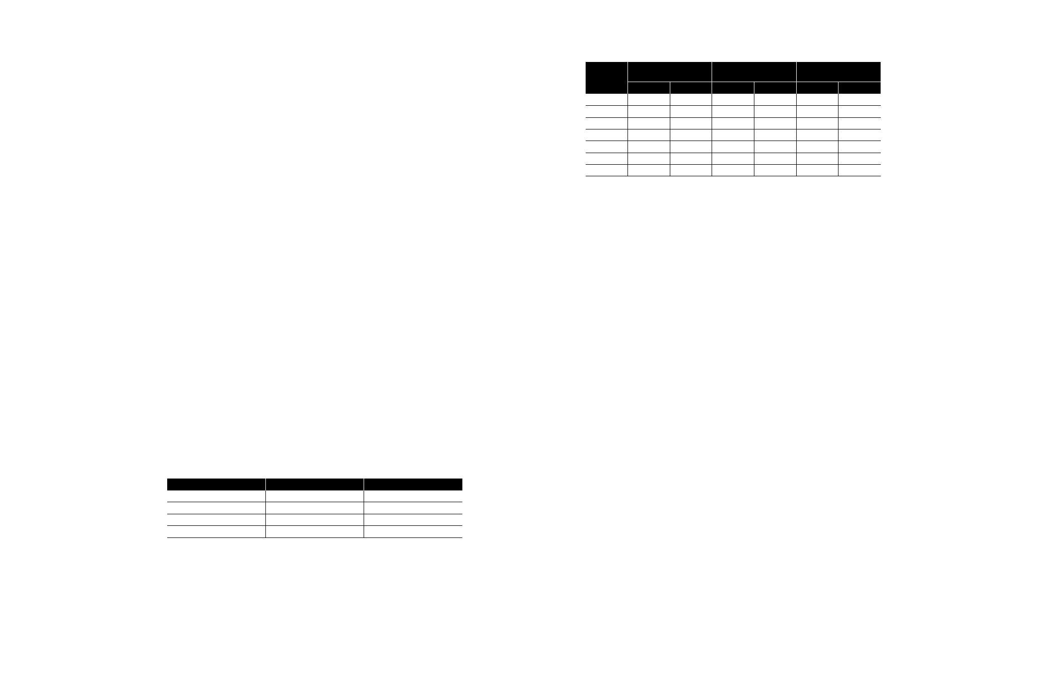
The network scan time for a Modbus Network depends on the number of registers requested
from each device and the number of devices attached to the network. Tables 4.1 and 4.2 provide
guidelines for calculating average field unit poll times and average network scan times. The Modbus
function code 03 was used to obtain this information.
Tables 4.1 and 4.2 do not include Host delay between each poll. Host delays between each poll are
variable for each Host. The Host turn-time from receipt of poll to issuance of next poll should be
greater than 20 ms and less than 50 ms.
Table 4.1 – Average Field Unit Response Time
Number of
MX-DDC Query Send/
UEC-3-DDC Query Send/
Registers
Receive Time (ms)
Receive Time (ms)
1
40
71
5
50
109
10
62
162
Note 1: Network Protocol - Modbus RTU
Communication Settings - 9600 baud, parity - none, data bits = 8, stop bits = 1
Network Cable - Belden 3074F, 3105A, and 9841
Table 4.2 – Average Network Scan Time (seconds)
Number of
Field Units
Scan Time 1 Register
per Field Unit
Scan Time 5 Registers
per Field Unit
Scan Time 10 Registers
per Field Unit
MX-DDC
UEC-3-DDC
MX-DDC
UEC-3-DDC
MX-DDC
UEC-3-DDC
10
.40
.94
.50
1.4
.61
1.9
20
.80
1.9
.98
2.8
1.3
3.8
40
1.6
3.9
2.0
5.6
2.5
7.6
50
2.3
5.0
2.9
7
3.8
9.6
100
4.6
11
6
15
6.5
20
200
9.2
24
10
32
13
43
250
11.5
32
12
42
16
56
Note 1: Network Protocol - Modbus RTU
Communication Settings - 9600 baud, parity - none, data bits = 8, stop bits = 1
Network Cable - Belden 3074F, 3105A, and 9841
Example
An MX-DDC Network with 20 field units with 5 registers per field unit being polled will have an
average total network scan time of .98 seconds. Host message turn-time per
field unit must be added to this number. (Typical open/close or close/open operating times for
motor-operated valves is 30 to 90 seconds.)
4.3.1 Network Communication Errors
In understanding how network communication errors should be handled, a brief discussion
defining the difference between field unit communication fault status and Host communication fault
status should be helpful. In a typical Limitorque DDC-100 Network, there are two levels of Channel
A and Channel B fault.
The first level is the field unit level. In each DDC-100 Field Unit, there are Channel A/B Fault bits
located in Register 9, bits 10 and 11 respectively. These bits are set by the field unit as a result of
successful communication with the Host over the network.
For UEC-3-DDC and I/O module-based field units, the Channel A bit monitors the standard
communication Channel A (ports A1 and A2) for redundant loop communications. The Channel B
bit monitors the optional Channel B (ports B1 and B2). Channel B is a second port that is used for
dual redundant loop communications.
In a redundant loop network with no faults, the UEC-3-DDC Field Unit will report Channel A with
no fault (Reg. 9, bit 10 – contents = 0), but Channel B will indicate a fault condition (Reg. 9, bit 11
– contents = 1). The Channel A fault bit is 0 because the field unit Channel A is active with no faults,
while Channel B is 1 because the optional granddaughter board for Channel B is not installed or in
use.
For MX-DDC-based field units, the Channel A bit monitors the communication Channel A1 (terminal
points 15 and 16) and the Channel B bit monitors communication Channel A2 (terminal points 29
and 41) for redundant loop communications (the MX-DDC does not support dual redundant loop
communications).
In a redundant loop network with no faults, the MX-DDC Field Unit will report Channel A with no
fault (Reg. 9, bit 10 – contents = 0) and Channel B with no fault (Reg. 9, bit 11 – contents = 0).
This level of communication-error reporting is used for local field unit communication diagnostics.
Should a Host not be able to communicate with a field unit, the Host will not be able to retrieve this
or any other status information to indicate error conditions.