Flowserve DDC-100 Modbus Direct-to-Host User Manual
Page 11
16
DDC-100 Direct-to-Host Programming Guide
FCD LMAIM4019-00
FCD LMAIM4019-00
DDC-100 Direct-to-Host Programming Guide
17
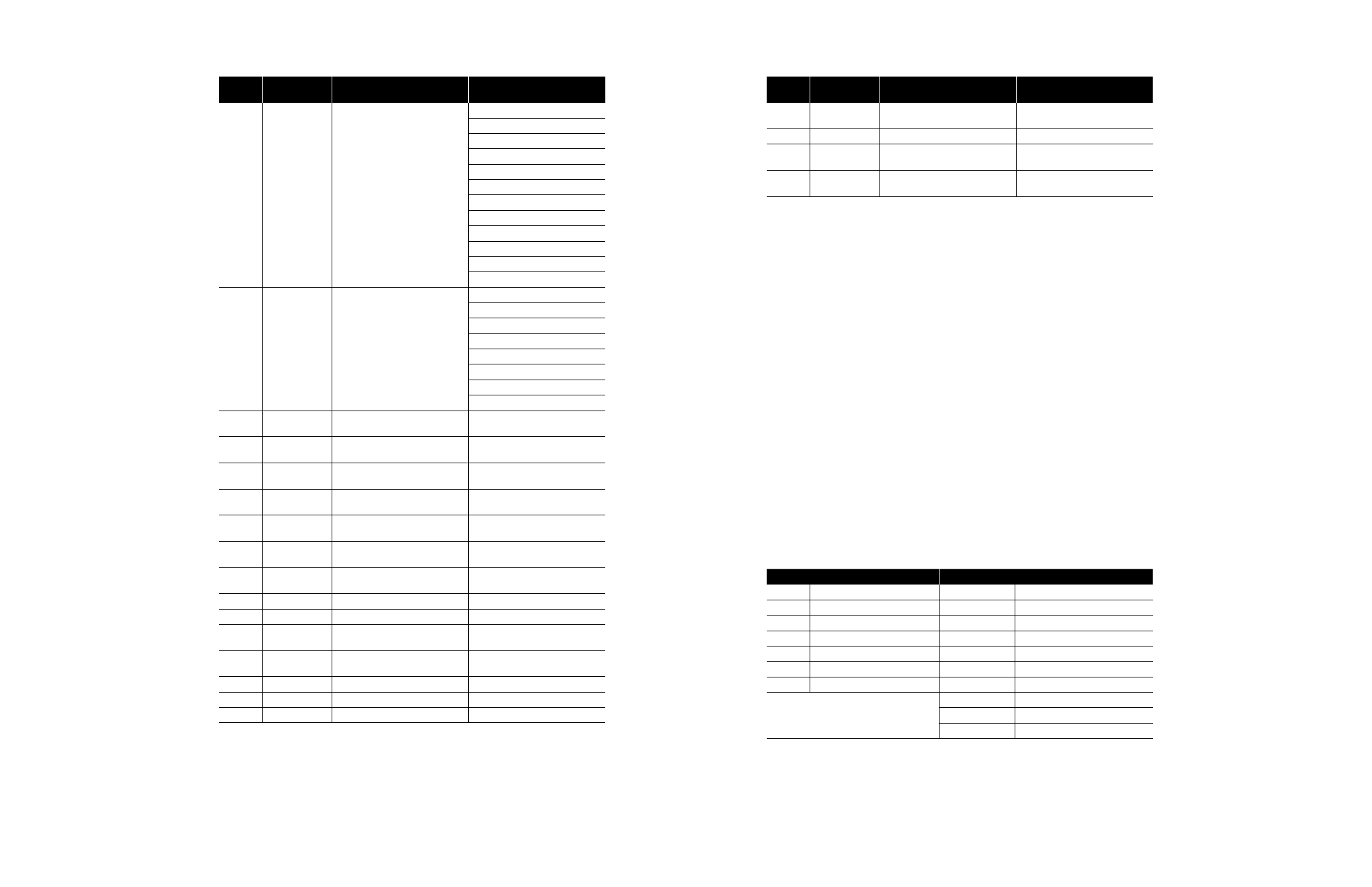
Table 3.5 – Field Unit Register Definitions (continued)
Register
Number
Register Name
MX/DDC Meaning
UEC-3-DDC Meaning
15
User Faults
Bits 1-15 – Not Used
Value of 16 Bits
Bit 0 User Fault 0
Bit 1 User Fault 1
Bit 2 User Fault 2
Bit 3 User Fault 3
Bit 4 User Fault 4
Bit 5 User Fault 5
Bit 6 User Fault 6
Bit 7 User Fault 7
Bit 8 User Fault 8
Bit 9 User Fault 9
Bits 10-15 Reserved
16
Current State
Bits 0-15 – Not Used
Value of 16 Bits
Bit 0 Waiting to Open
Bit 1 Waiting to Close
Bit 2 Running Backward
Bit 3 Invalid Configuration
Bit 4 Reverse Switches
Bit 5 OK to Modulate
Bits 6-15 Reserved
17
Field Unit
Holding Register
Special Applications Only
Special Applications Only
18
Field Unit
Holding Register
Special Applications Only
Special Applications Only
19
Field Unit
Holding Register
Special Applications Only
Special Applications Only
20
Field Unit
Holding Register
Special Applications Only
Special Applications Only
21
Field Unit
Holding Register
Special Applications Only
Special Applications Only
22
Field Unit
Holding Register
Special Applications Only
Special Applications Only
23
Field Unit
Holding Register
Special Applications Only
Special Applications Only
24-44
Reserved
Special Applications Only
Special Applications Only
45-47
Not Named
Special Applications Only
Special Applications Only
48
TP_START_
POSITION
Special Applications Only
Special Applications Only
49
TP_STOP_POSI-
TION
Special Applications Only
Special Applications Only
50
TP_SAMPLE
Special Applications Only
Special Applications Only
51
TP_MID_T_HIGH Special Applications Only
Special Applications Only
52
TP_MID_T_POS Special Applications Only
Special Applications Only
Table 3.5 – Field Unit Register Definitions (continued)
Register
Number
Register Name
MX/DDC Meaning
UEC-3-DDC Meaning
53
TP_MID_T_AV_
VAL
Special Applications Only
Special Applications Only
54
TP_STOP_VAL
Special Applications Only
Special Applications Only
55
TP_BEFORE
MID_T_HIGH_
Special Applications Only
Special Applications Only
56
TP_AFTER
MID_T_HIGH
Special Applications Only
Special Applications Only
Note 1: Torque will be expressed proportionally as a reference only from 40-100% inclusive. Initial indication
may read 0% until torque exceeds 40% minimum.
Note 2: Default value is scaled 0-100 of span. Changes made to “Scale Analog” affect Analog registers (3, 4,
6, 7, 8) and “move-to” commands.
Note 3: Combined Fault bit is a value of 1 or true when bit 5 or 8 or 9 or 15 or (bits 10 and 11) is a value of 1
or true.
Note 4: Channel A is physical connection A1. Channel B is physical connection A2.
MX/DDC actuators shipped prior to 2nd QTR, 1999, have the following definition for Register 9 bit 6. When
this bit has a value of 1 or true, the actuator selector switch is in LOCAL mode. This bit does not indicate
STOP or REMOTE. The actuator selector switch in REMOTE (available for network control) is indicated by
Register 12 bit 00 having a value of 1 or true. Register 9 bit 6 value 0 (zero) or false AND Register 12 bit 00
value 0 (zero) or false indicates selector switch is in the STOP position.
MX/DDC actuators shipped after 2nd QTR, 1999, have the following definition of Register 9 bit 6. When this
bit has a value of 1 or true, the actuator is in LOCAL or STOP (unavailable for network control). The actuator
selector switch in REMOTE (available for network control) is indicated by Register 12 bit 00 having value
of 1 or true.
IMPORTANT: Verify Host program when installing an MX/DDC actuator shipped after 2nd QTR, 1999, on a
network commissioned before 2nd QTR, 1999, for indication of selector switch values. Proper selector switch
indication at the Host will ensure safe conditions at the facility.
Example
Poll field unit number 125 for 3 registers starting at register 8 with the actuator stopped between
the limits and in local mode.
Query 7D0300070003BFF6
Response 7D0306003D084400003E07
Message Breakdown
Query
Response
7D
Slave (Field Unit) Address
7D
Slave (Field Unit) Address
03
Function
03
Function
00
Starting Address Hi
06
Byte Count
07
Starting Address Lo
00
Data Hi (Register 40008)
00
No. of Points Hi
3D
1
Data Lo (Register 40008)
03
No. of Points Lo
08
Data Hi (Register 40009)
BFF6
Error Check (CRC)
44
2
Data Lo (Register 40009)
00
Data Hi (Register 40010)
00
Data Lo (Register 40010)
3E07
Error Check (CRC)
Note 1: 003Dh equals 61 Decimal (actuator Analog Input 1 in percent format).
Note 2: 0844h equals 2116 Decimal or 0000 1000 0100 0100 Binary (actuator stopped between limits, local
mode, and Channel B Fail bit is ON).