Figure 4.1 – ddc-100 redundant loop network, Figure 4.2 – ddc-100 single-ended loop network, 2 single-ended loop – Flowserve DDC-100 Modbus Direct-to-Host User Manual
Page 18: Host
30
DDC-100 Direct-to-Host Programming Guide
FCD LMAIM4019-00
FCD LMAIM4019-00
DDC-100 Direct-to-Host Programming Guide
31
2 on the Host. The Host is not required to act on the data received at the second port. Note that,
because of the bi-directional nature of the serial ports, the direction of data flow can be reversed.
Communications can be initiated by port 2 of the Host to port A2 of the first field unit. This data is
then transmitted out port A1 to port A2 of the next field unit. The data then continues in this direc-
tion until it reaches port 1 of the Host. In either direction, the signal is regenerated in each field unit
to permit longer-distance communications with reduced noise sensitivity and improved reliability.
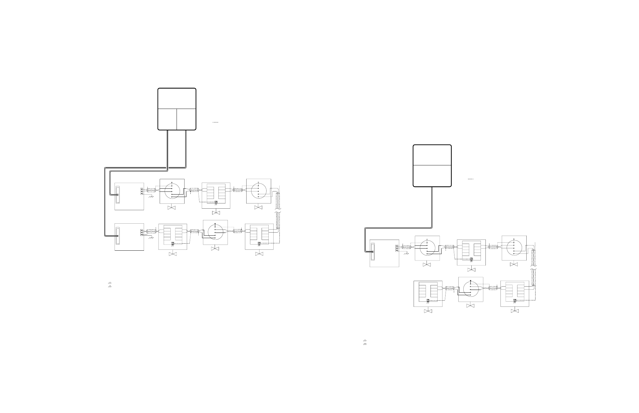
Figure 4.1 – DDC-100 Redundant Loop Network
RS-232
RS-232
RS-485
Diagnostic Note:
Earth Ground Note:
MOV-2
A2
A2*
A1
A1*
TB5
MOV-248
A1
A1*
A2
A2*
TB5
N/C
MOV-250
D-M
D-M*
D-S
D-S*
A1
A1*
A2
A2*
TB4
TB3
TB5
Notes:
Legend
MOV
D-M
D-M*
D-S
D-S*
N/C
Data terminal is positive with respect to data* terminal
RS-232 to RS-485
converter with
surge suppression
Data 1
See Note 5
See Note 5
See Note 5
Earth Ground
(See Note 4)
RS-232 to RS-485
converter with
surge suppression
1) Belden 3074F, 3105A, or 9841 shielded cable is recommended.
2) Correct polarity for field unit and network controller
connection is necessary for proper operation.
3) Connections shown are typical. The number of
MOVs shown may not indicate true system size.
4)
Earth ground: ground rod
5)
Earth ground: ground rod or lug in
actuator if actuator is grounded.
Polarity and level of the network’s data connection can
be checked by measuring voltage between data and
data* terminals. This voltage should be greater than
+200 mVDC with network controller network ports
disconnected.
If low impedance earth ground is not available at
each actuator, contact engineering for alternative
earth ground surge protection strategies.
Host
RS-232
PORT 1
Network Port A
RS-232
PORT 2
Network Port B
A1*
MOV-1
See Note 5
N/C
A2*
N/C
MOV-249
See Note 5
N/C
MOV-3
See Note 5
N/C
16
15
41
29
29
41
D-S
D-S*
D-M
D-M*
TB3
TB4
D-M
D-M*
D-S
D-S*
TB4
TB3
Ground 3
Data* 2
RS-485
Data 1
Data* 2
15
16
A2
A1
A1*
A2*
29
41
15
16
A2
A1
A1*
A2*
29
41
15
16
A2
A1
- Motor-Operated Valve
- Data A1
- Data A1*
- Data A2
- Data A2*
- Data A1 (UEC-3-DDC)
- Data A1*(UEC-3-DDC)
- Data A2* (UEC-3-DDC)
- Shield
- No Connection
- Data A2 (UEC-3-DDC)
N/C
Earth Ground
(See Note 4)
Ground 3
N/C
4.2.2 Single-Ended Loop
The single-ended loop topology is the loop topology described above except that only one end of
the loop is connected to the Host as shown in Figure 4.2. The single-ended loop is wired by cabling
from the Host port to the first field unit port A1. Port A2 of this field unit is then connected to port
A1 of the next field unit. This continues until the last field unit is connected. (If a stub cable is run
from port A2 of the last field unit to a planned field unit location, or the last field unit is discon-
nected, the end of the cable must be terminated with a 120 ohm resistor to prevent unacceptable
signal reflections.) The connection of the single-ended loop is identical to the redundant loop except
that in the single-ended loop the connection from the last field unit to port 2 of the Host is omitted.
The single-ended loop topology utilizes the field unit repeater circuitry that maximizes the number
of field units and distance inherent with the loop topology. The single-ended loop is inherently less
reliable than the redundant loop topology because the Host can only reach the field units from one
direction. It is, however, more reliable than the single-line multi-drop because a break or a short will
only prevent communication with the field units beyond the break or short.
Figure 4.2 – DDC-100 Single-Ended Loop Network
RS-232
RS-485
Diagnostic Note:
Earth Ground Note:
MOV-2
A2
A2*
A1
A1*
TB5
MOV-248
A1
A1*
A2
A2*
TB5
MOV-250
D-M
D-M*
D-S
D-S*
A1
A1*
TB4
TB3
TB5
Notes:
Legend
MOV
D-M
D-M*
D-S
D-S*
N/C
Data terminal is positive with respect to data* terminal
RS-232 to RS-485
converter with
surge suppression
Data 1
See Note 5
See Note 5
See Note 5
1) Belden 3074F, 3105A, or 9841 shielded cable is recommended.
2) Correct polarity for field unit and network controller
connection is necessary for proper operation.
3) Connections shown are typical. The number of
MOVs shown may not indicate true system size.
4)
Earth ground: ground rod
5)
Earth ground: ground rod or lug in
actuator if actuator is grounded.
Polarity and level of the network’s data connection can
be checked by measuring voltage between data and
data* terminals. This voltage should be greater than
+200 mVDC with network controller network ports
disconnected.
If low impedance earth ground is not available at
each actuator, contact engineering for alternative
earth ground surge protection strategies.
A1*
MOV-1
See Note 5
N/C
A2*
N/C
MOV-249
See Note 5
N/C
MOV-3
See Note 5
N/C
16
15
41
29
29
41
D-S
D-S*
D-M
D-M*
TB3
TB4
D-M
D-M*
D-S
D-S*
TB4
TB3
Ground 3
Data* 2
15
16
A2
A1
A1*
A2*
29
41
15
16
A2
A1
A1*
A2*
29
41
15
16
A2
A1
- Motor-Operated Valve
- Data A1
- Data A1*
- Data A2
- Data A2*
- Data A1 (UEC-3-DDC)
- Data A1*(UEC-3-DDC)
- Data A2* (UEC-3-DDC)
- Shield
- No Connection
- Data A2 (UEC-3-DDC)
N/C
Earth Ground
(See Note 4)
N/C
Host
RS-232
PORT 1
Network Port A