Flowserve PSS III Durametallic User Manual
Page 7
7
Figure 9
Figure 10
since too much adhesive impedes
gasket flexibility and can lead to
excessive leakage.
4.6 Push the end into the adhesive
and check the gasket extension
with the height gauge. Hold it in
place for 10 seconds.
See Figure 9.
4.7 Glue the other end of the sleeve
gasket in the groove using the
same procedure.
4.8 Push the draped middle of the sleeve gasket and rotating face
gasket into their grooves. Make sure these gaskets are fully
seated in their grooves. Do not apply adhesive. See Figure 7.
4.9 Repeat these steps for the rotating face gasket again noting the
chamfer location.
4.10 Repeat this procedure for the other seal drive half.
5 Seal Drive Split Joint Gasket and Cap Screw
Installation
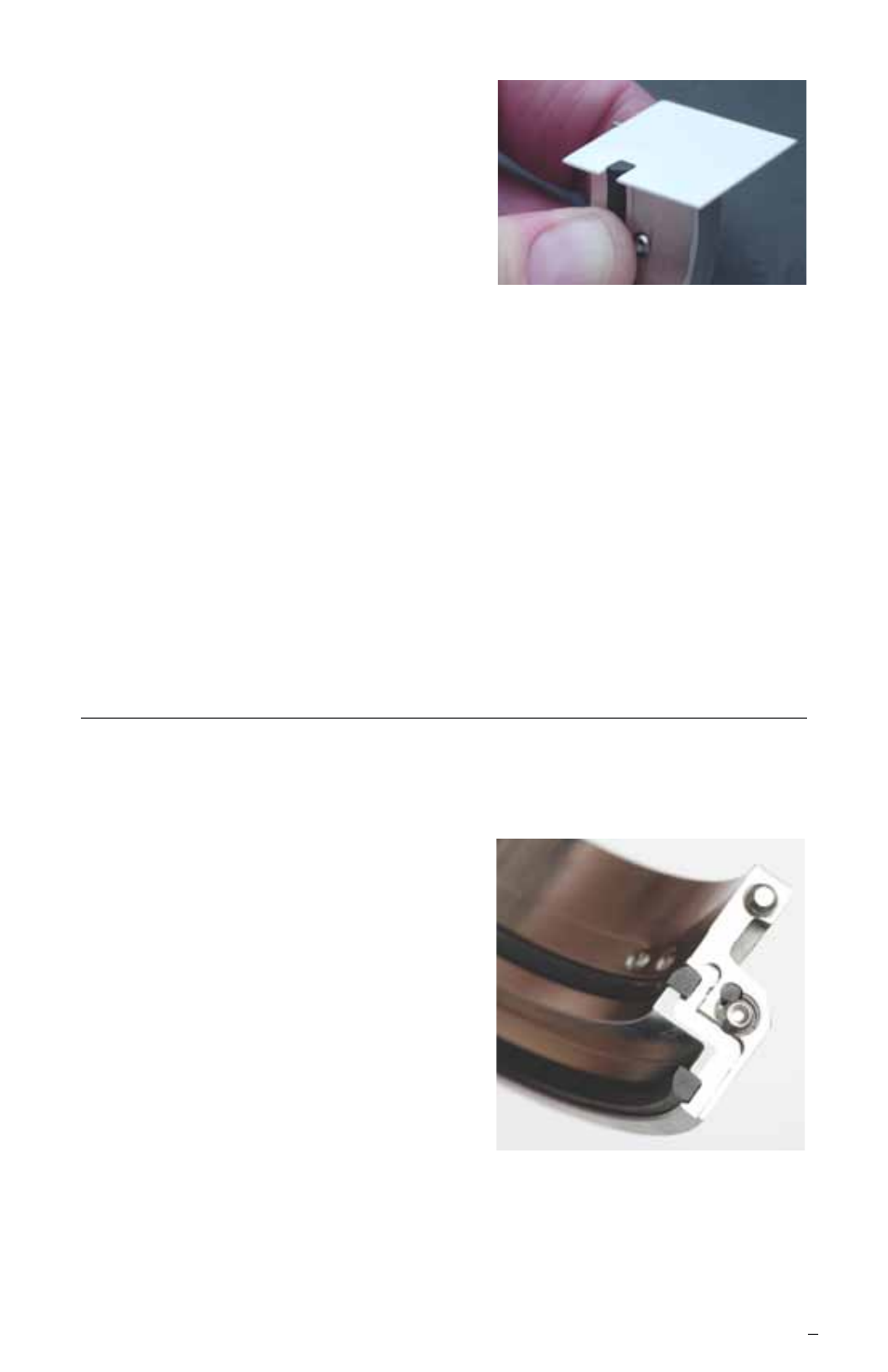
5.1 Each seal drive half has split gasket grooves machined into
each joint surface. The split joint gasket can be installed in
either groove so long as the gaskets are located 180° apart
when the seal drive is fully
assembled. See Figure 10.
5.2 Wipe the proper split joint gasket
groove clean with alcohol.
Caution: Consult material safety data
sheets for proper handling of
alcohol.