10 gland split joint gasket installation – Flowserve PSS III Durametallic User Manual
Page 12
12
9.5 Push the end into the adhesive
and check the gasket extension
with the height gauge. Hold it
in place for 10 seconds.
See Figure 25.
9.6 Glue the other seat gasket end
into the groove using the same
steps.
8.7 Push the draped middle of the
gasket into the groove. Make
Figure 25
sure this gasket is fully seated in the groove. Do not apply adhesive.
9.8 Repeat this procedure for the other gland half.
the groove of the joint surface
where the threaded cap screw
holes are located.
10.3 Wipe the gland split joint gasket
groove clean with alcohol.
Caution: Consult material safety data
sheets for proper handling of
alcohol.
Note: Care must be taken to avoid
getting the adhesive too close
to the seat gasket or the gland
gasket. These should not be
glued together.
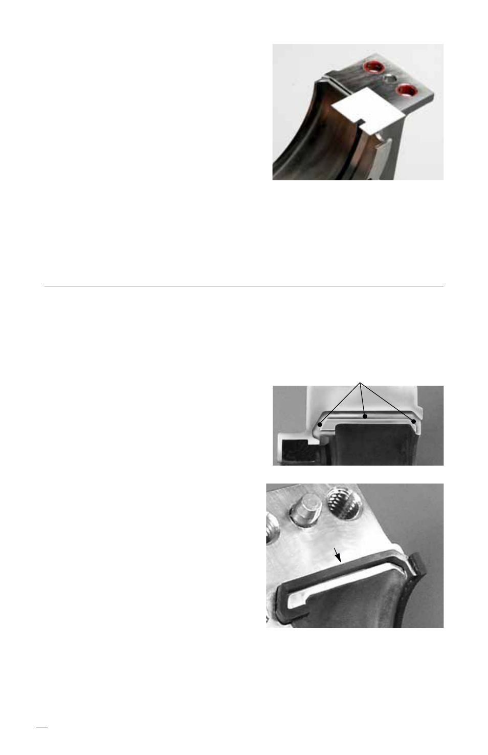
10.4 Put three dots of adhesive in the
groove as shown in Figure 26.
10.5 Place the split joint gasket in the
groove. The split joint gasket
Figure 27
Figure 26
Adhesive dot here
should be flush with the gland gasket groove surface, top of the
seat gasket, and top of the split joint gasket groove. Hold it in place
for 10 seconds. See Figure 27.
10.6 Repeat this procedure for the other gland half.
10 Gland Split Joint Gasket Installation
10.1 Loosen the gland cap screws and completely separate the gland
halves.
10.2 Each gland half has split joint gasket grooves machined into
each joint surface. The split joint gasket should be installed in
Flush