1 disassemble and clean, 2 ongoing inspection – Flowserve PSS III Durametallic User Manual
Page 4
4
1 Disassemble and Clean
1.1 Remove the cap screws from the seal drive and gland.
1.2 Remove the rotating and stationary face halves by lifting the
center of each face up above their drive or lock pins and sliding
the face away from the seal drive or gland.
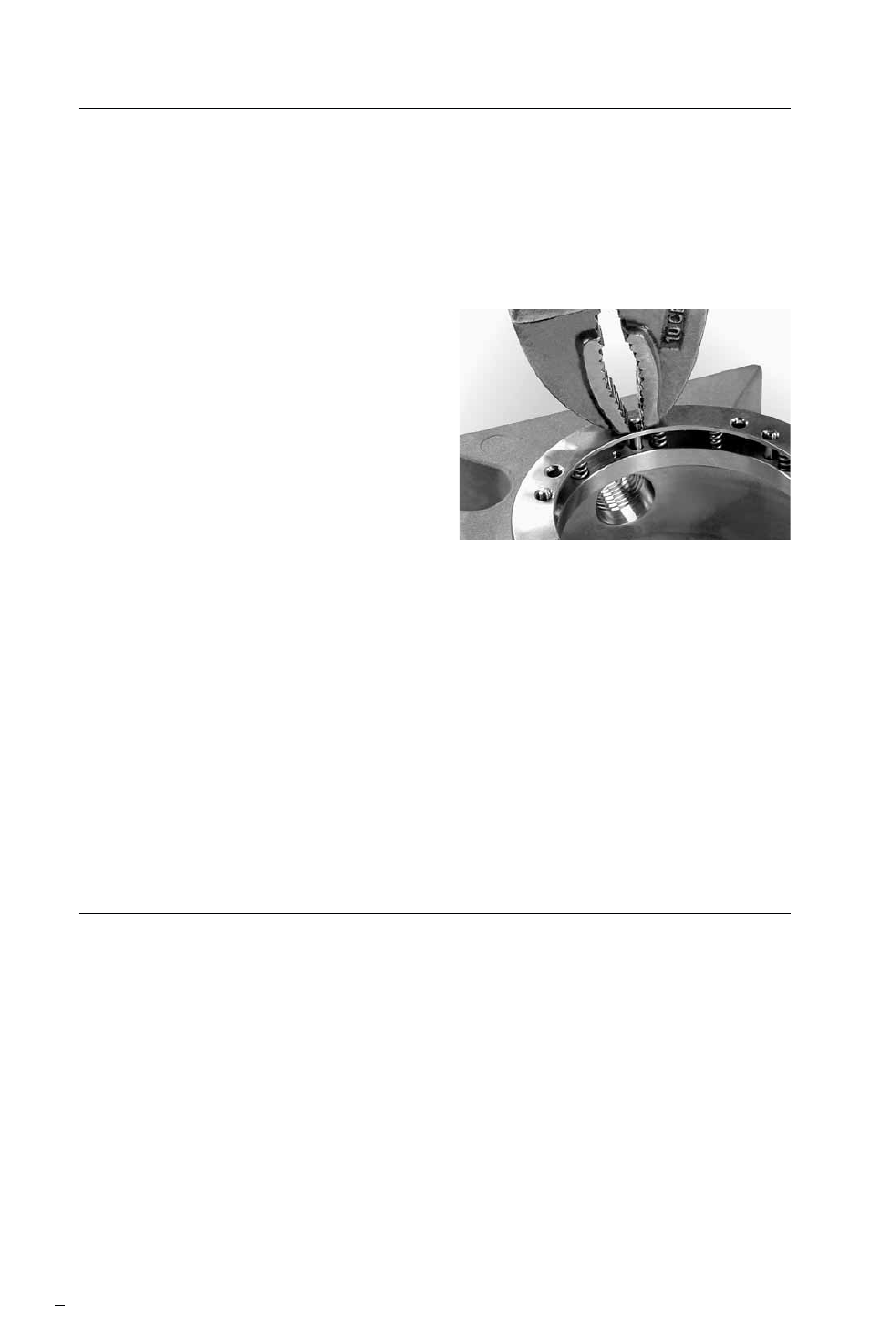
1.3 Remove the spring holder by pulling out the lock pins. See Figure 2.
1.4 Soak the parts in a solvent
to remove the secondary
seals, cap screw retainers and
retaining sleeves, adhesive,
grease, etc. Suggested solvents
include:
• Loctite X-NMS 768
• Acetone
• Trichloroethane (chlorothene)
Note: Follow all Material Safety Data
Sheet (MSDS) recommendations when handling these fluids.
1.5 Remove any remaining adhesive by brushing or lightly scraping.
1.6 Wash parts in hot soapy water. Rinse thoroughly in clean water.
Let parts dry.
Caution: Do not sand or bead blast gasket and joint surfaces in the
seal drive and gland to avoid damaging them. Glue, rubber, or
heavy deposits must be carefully scraped off these surfaces
before installing the gaskets.
2 Ongoing Inspection
During the assembly process follow these inspection procedures to avoid
errors which may not be correctable later.
2.1 Check Adhesion - Gently tug at the gaskets to be sure they are
properly secured. If they come loose easily, it is likely that the
surfaces were not adequately cleaned or rinsed. Clean the surface
again and reapply adhesive per the instructions. Apply small dots
of adhesive only where specified. Dot size should be 1.00 to
2.00 mm (0.040 to 0.080 inch) in diameter.
2.2 Gasket Length - Be sure that the rotating face gasket, stationary
face seat gasket, and seal drive sleeve gasket are 0.65 to 0.90 mm
(0.025 to 0.035 inch) longer than the surfaces where they end.
See Figure 3. If they are not, reposition them accordingly.
Figure 2