Flowserve FRBH User Manual
Page 40
FRBH, FRBHX AND FRBHS USER INSTRUCTIONS ENGLISH 71569178 10-04
Page 40 of 54
®
soft and pliable. If stuffing box friction is so great that
the pump shaft cannot be turned by hand, the box is
not properly packed.
6.10.11.2 Mechanical seal
&
Refer to any special instructions supplied with
the mechanical seal.
a) Before the mechanical seal can be installed, the
pump must be assembled with the correct impeller
running clearances (ie: all assembly steps above). A
scribe mark is then placed on the circumference of
the sleeve to mark the end of the box. This mark is
used to locate the seal position referenced by the
mechanical seal drawing provided.
b) After scribing the sleeve, remove the rotating
element from the casing. Do not adjust the bearing
housing.
c) Remove the impeller nut [24], impeller [2], impeller
key [32] and stuffing box head [11]. Assemble the
mechanical seal components, including gland plates,
gaskets and rotating parts over the sleeve. Locate
the seal relative to the scribed markings on the shaft
sleeve [14] as indicated by the seal manufacturers’
instruction.
d) Remove lubricating compound from the impeller nut
and shaft threads. Re-assemble components in
accordanc e with original assembly procedure with
the exception that Loctite 242 is applied to the
impeller nut [24] threads. Torque the nut in
accordance with information below.
MINIMUM IMPELLER NUT
TIGHTENING TORQUE
FRAME
Ft. lbs.
Nm.
1
100
140
2
300
400
3
300
400
4
550
750
e) Assemble the mechanical seal gland plate and
gasket and fasten using gland studs [209]. Secure
with nuts [215] and tighten each by hand. Further
tighten the nuts in accordance with Table in 6.6.
Rotate the shaft to ensure that it turns freely without
rubbing or binding.
f) Re-assemble the rotating element into the casing.
Do not adjust the thrust bearing housing.
g) Set the deflector [40] at the line bearing cover [35] so
that they do not contact when the shaft is rotated.
Lock in place with the setscrews provided.
6.10.11 Final assembly
a) Lift the assembled pump onto the baseplate and
position the casing feet over the tapped holes in the
baseplate.
b) On all sizes except the 18FRBH-274, loosen the
bolts that attach the read support foot [191] to the
bearing frame [19]. Level the unit and align with the
piping. Tighten the bolts attaching the casing feet to
the baseplate in accordance with Table 6.6 using for
tightening torques. Do not distort casing or frame.
c) Install the pump coupling or sheave as required.
d) Refer to Section 4, Installation and Section 5,
Preparation for Operation.
e) It is recommended that the pump not be packed until
required. Refer to stuffing box packing procedure in
this section. Protect the stuffing box bore and seal
area with clean dry rags.
6.11 Impeller axial clearance adjustment
6.11.1 FRBH and FRBHX Units
This procedure should not be used on units
with mechanical seals if the design is such that a
liquid seal cannot be maintained when the rotor is
moved axially against the wear plate.
Unless seal is a cartridge design it may not be
possible to adjust the shaft unless the pump is
dismantled.
&
Refer to any special instructions supplied with
the mechanical seal
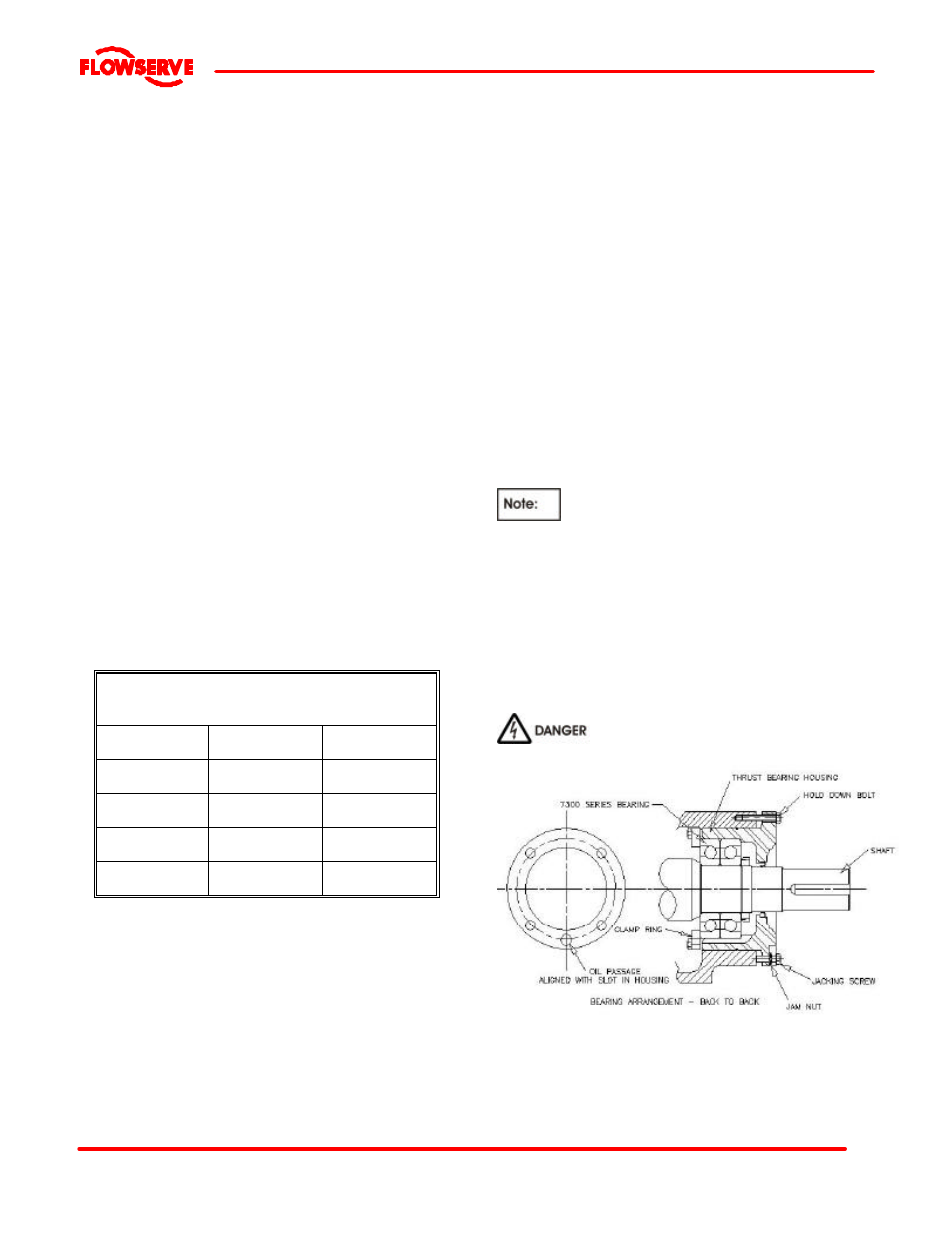
NEVER ATTEMPT TO CHANGE THE
CLEARANCE WHEN THE PUMP IS RUNNING.
If the coupling has limited axial adjustment capability,
the pump and driver must be uncoupled prior to
adjusting the clearance in order to permit free
movement.