Flowserve VCT User Manual
Page 13
USER INSTRUCTIONS APM, APMA and APH MX0301 - 07/03
Page 13 of 32
®
Refer to the manuals of any associated
equipment for periodic checks needed.
6.2 3 Re-lubrication
Refer to the motor manual and any
associated equipment for periodic checks needed.
6.3 Spare parts
6.3.1 Ordering of spares
Flowserve keep records of all pumps that have
been supplied. When ordering spares the following
information should be quoted:
1) Pump serial number
2) Pump size
3) Part name – taken from sectional drawing
in attachment.
4) Part number – taken from sectional
drawing in attachment.
5) Number of parts required
The pump size and serial number are shown on the
pump nameplate.
If over size or under size parts are required (liked to
wear rings) a sketch is required with indication of
diameter dimension required.
To
ensure
continued
satisfactory
operation,
replacement
parts
to
the
original
design
specification should be obtained from Flowserve.
Any change to the original design specification
(modification or use of a non-standard part) will
invalidate the pump’s safety certification. For
Flowserve contact see section 10 at the end of
these user instructions.
6.3.2 Storage of spares
Spares should be stored in a clean dry area away
from vibration. Inspection and re-treatment of
metallic surfaces (if necessary) with preservative is
recommended at 6 monthly intervals.
6.4 Recommended spares and
consumable items
For start up purposes:
1 - complete set of packing
1 - set of gaskets and o rings
For 2 years operation:
1 - set of bearings
1 - set of packing
1 - shaft sleeve
1 - set of gaskets
1 – set of casing wear rings
(optional:
1 - impeller wear rings)
For 4 years operation:
1 - set of bearings
1 - sets of gland packing
1 - shaft sleeves
1 - set of gaskets
1 - set of casing wear rings
1 - impeller
(optional:
1 - impeller wear rings)
6.5 Tools required
Any special tool is required to maintain these
pumps.
6.6 Fastener torques
6.6.1 Flange mating
Surfaces shall be thoroughly cleaned. Assemble
joint and hand tighten all fasteners to insure
uniform metal-to-metal contact of the mating
surfaces.
6.6.2 Using the proper size torque wrench
( Work in ¼ to ¾ of wrench scale ) Pretorque
fasteners with an even steady pull to approximately
1/3 of the torque value in the sequence specified
below. Repeat sequence increasing torque to
approximately 2/3 of the specified value.
Finally repeat sequence for the specified torque.
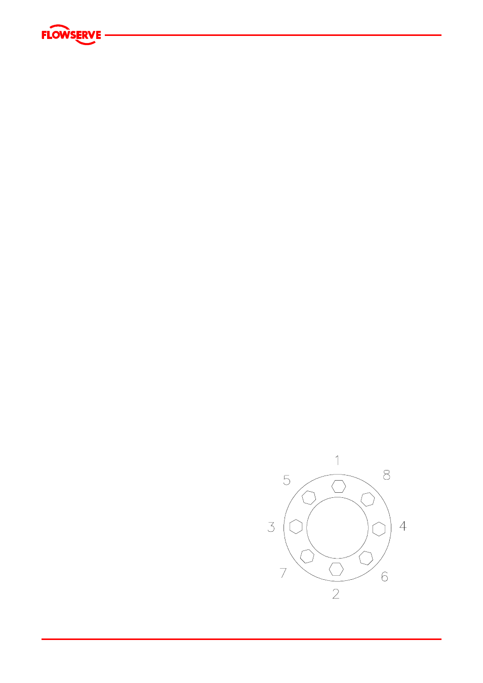
6.6.3 start with any bolt
Identify as (1) and location designated as 0°, bolt
(2) will be at 180°, bolt (3) at 270° , and bolt (4 ) at
90°, Using counterclockwise rotation, tighten bolt
(5), (see figure below , where number of bolts are
only as example) and continue rotation until all
bolts have been tightened.