Flowserve VF User Manual
Page 25
VF USER INSTRUCTIONS ENGLISH 71561233 - 11/09
Page 25 de 32
6.2.4 Mechanical seals
The current maintenance is limited to seal control.
It is necessary to detect any small leakage which
announces the beginning of the deterioration of
friction faces or secondary seal elements (rings,
bellows, synthetic membranes). It is advisable to
stop the pump as soon as possible. Have an
approved seal vendor replace or repair the seal.
6.2.5 Gland packing
6.2.5.1 Pump fitted with a packed gland
A well run in and correctly adjusted packing gland
requires little maintenance.
If, after some time, the leakage becomes too great,
the gland should be tightened again in order to
return these to a normal level.
If re-tightening is not possible, new packing must
be installed.
6.2.5.2 Gland packing inspection and removal
a) Remove the shield guards
b) Slide back the gland.
c) Remove the packing rings with an extractor
designed for this purpose (including the
lantern ring if it exists; note its position and its
direction of rotation).
d) Inspect the state of the sleeve surface; the
presence of many marked grooves will
indicate that it must be replaced.
e) Carefully clean the different pieces of the
packing gland.
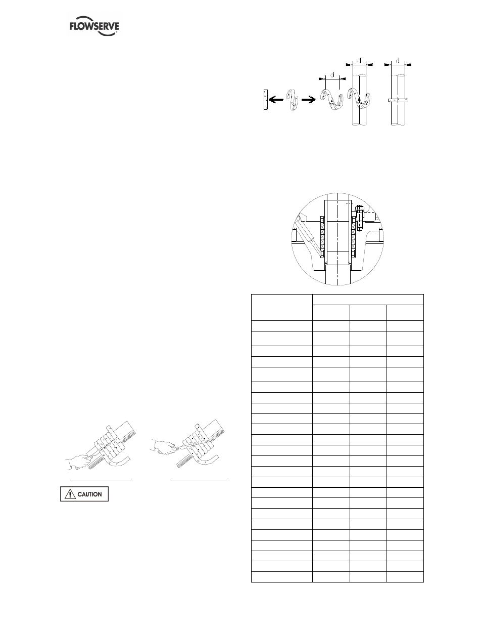
6.2.5.3 Gland packing fitting
If the packing is supplied as cord the packing must
be cut so that the external diameter is lightly
tightened and there is an initial gap between the
sleeve and the packing ring.
For that purpose, wind the packing helically around
the shaft sleeve or a chuck of the same diameter.
(Take precautions to avoid damaging sleeve).
Example of straight cut
Example of bevel cut
Ensure a tightening on the stuffing
box housing and not on the sleeve.
SETTING OF PACKING
Follow the instructions:
a) Assembly of the packing in S.
b) Staggering by about 90° between two
packings.
c) Assemble packing after packing.
After setting the last packing, fix the gland on the
packings and screw up the nut by hand.
After this screwing phase, the shaft should turn by
hand as easily as before the setting of the
packings.
PACKING
PUMP TYPE
Quantity
(in mm)
Length (in
mm)
VF 40-20
≤
3 stages
6
10 x 10
160
VF 40-20
3 < stages
≤
6
6
10 x 10
175
VF 40-20 > 7 stages
6
12 x 12
230
VF 60-18
≤
3 stages
6
10 x 10
160
VF 60-18
3 < stages
≤
6
6
10 x 10
175
VF 60-18 > 7 stages
6
12 x 12
230
VF 78-37
6
12 x 12
230
VF 95-27
≤
2 stages
6
10 x 10
175
VF 95-27 > 2 stages
6
12 x 12
230
VF 180-27 1 stage
6
10 x 10
175
VF 180-27 > 1 stage
6
12 x 12
230
VF 190-19 1 stage
6
10 x 10
175
VF 190-19 > 1 stage
6
12 x 12
230
VF 185-35 1 stage
6
12 x 12
230
VF 185-35 > 1 stage
6
14 x 14
315
VF 250-43 1 stage
6
12 x 12
230
VF 250-43 >1 stage
6
14 x 14
315
VF 240-51 1 stage
6
12 x 12
230
VF 240-51> 1 stage
6
14 x 14
315
VF 300-37
6
14 x 14
315
VF 310-25
6
14 x 14
315
VF 460-31
6
14 x 14
315
VF 550-29 1 stage
6
14 x 14
315
VF 550-29 > 1 stage
6
16 x 16
396