Flowserve Guardian Sealless Metallic User Manual
Page 43
GUARDIAN USER INSTRUCTIONS ENGLISH 71569212 08-11
Page 43 of 68
flowserve.com
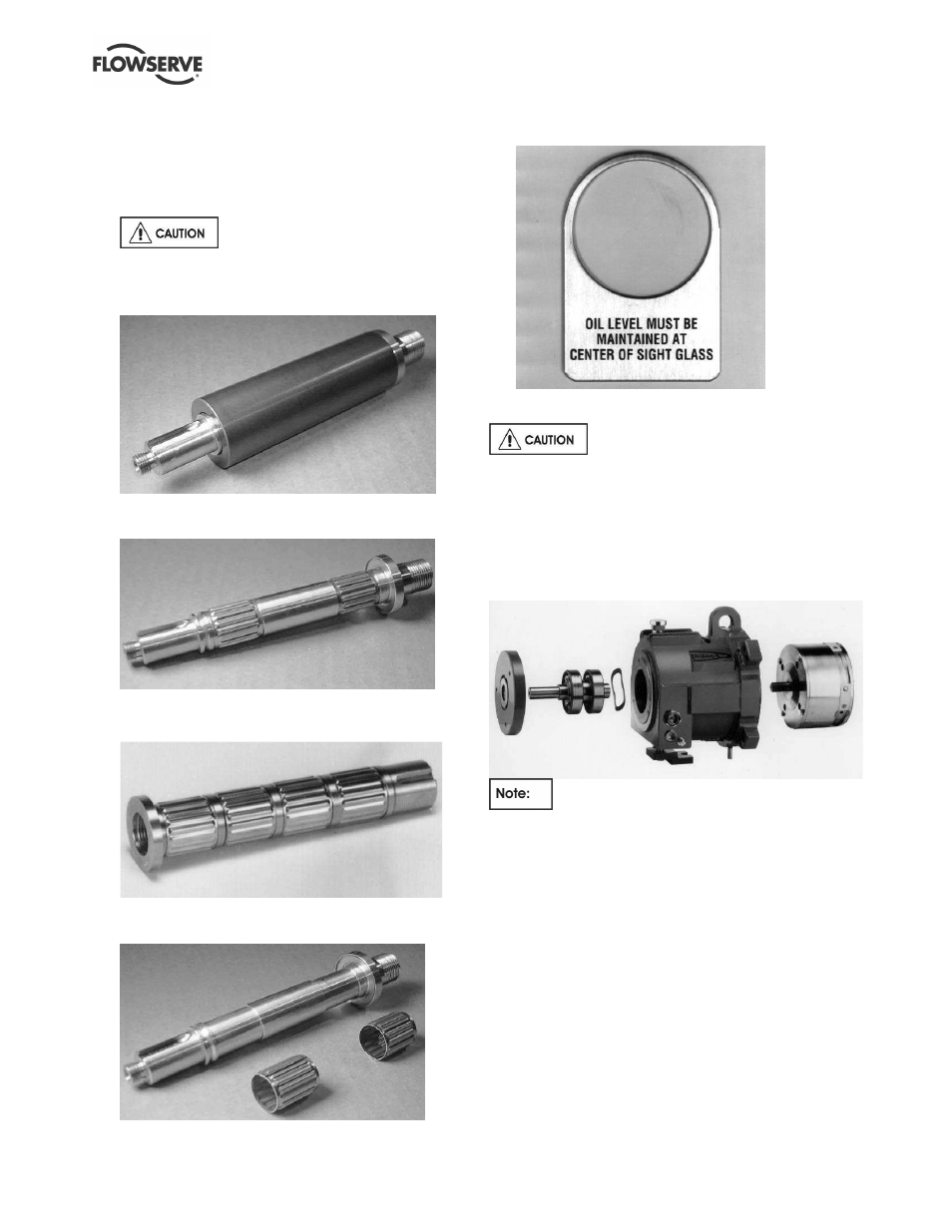
j)
To remove the pump shaft journal [213] from the
pump shaft [2100.1]. (Figure 6-16.) Wrap the
part in a rag and strike the pump shaft journal
[213] with a hard object to break it. Remove the
shaft gasket [4590.6] and discard. (Figure 6-17.)
Remove the tolerance rings [241] and discard.
Do not reuse the tolerance rings.
The disassembly of the wet end is now complete.
Figure 6-16: Group 1 pump shaft/journal
assembly
Figure 6-17: Group 1 shaft with mounted
tolerance rings
Figure 6-18: Group 2 shaft with mounted
tolerance rings
Figure 6-19: Group 1 shaft with unmounted
tolerance rings
Figure 6-20: “Oil level must be maintained at
center of sight glass”
6.7.5
Disassembling the power end
Be aware of strong magnetic forces of
the outer magnets. Keep magnetic material away
from these magnets. Observe previous warnings
concerning these magnets.
6.7.5.1
Long-coupled Guardian G & H series
pumps
Figure 6-21: Power end major components
This procedure is necessary if the outer
magnet assembly, anti-friction bearings or oil seals must
be replaced. See Figure 6-52 for recommendations on
ball bearing relubrication intervals.
a) Drain the oil in the bearing housing by removing
the bearing housing drain plug [6569.1]. Put the
bearing housing drain plug back into place after
the bearing housing is drained.
b) Remove reverse rotation screw [6570.8] with hex
head wrench. The threads are right hand.
c) Unscrew the outer magnet/flange assembly
[230/231] from the drive shaft [2100.2]. Mount
the drive shaft/coupling key [6700] and a Durco
impeller wrench on the shaft. With the wrench
handle pointing to the right when viewed from the
magnet side of the bearing housing [3200], grasp
the magnet firmly.