3 design of major parts – Flowserve Guardian Sealless Metallic User Manual
Page 12
GUARDIAN USER INSTRUCTIONS ENGLISH 71569212 08-11
Page 12 of 68
flowserve.com
3.3 Design of major parts
3.3.1
Pump casing and impeller
Removal of the casing is not required when
performing maintenance of the rotating element. The
pump is designed with a gasket perpendicular to the
shaft allowing the rotating element to be easily
removed (back pull out). The impeller is reverse
vane; there is no option for an open impeller.
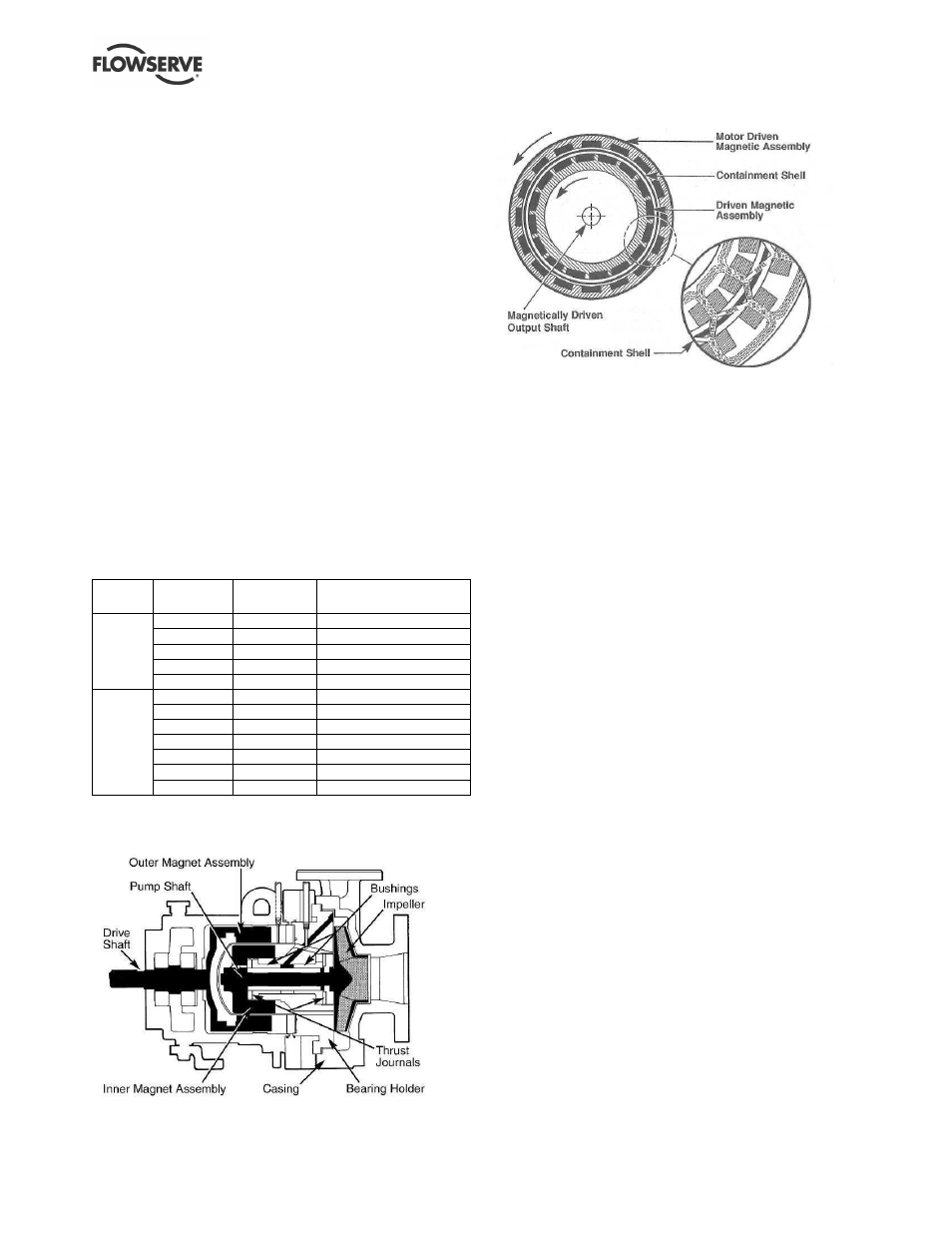
3.3.2
Magnetic coupling
See Figure 3-2 for magnetic coupling static torque
values. Outer and inner magnets are separated by a
containment shell which isolates the process fluid
from the atmosphere. When the motor drives the
outer magnet, the attraction between the outer and
inner magnet causes the pump shaft and impeller to
rotate. See Figure 3-3. This “magnetic coupling” is
produced by alternating polarities between the
magnet pairs on the inner and outer magnet
assemblies. The alternating magnet polarity also
causes repulsion between adjacent magnets and
prevents the coupling from slipping or decoupling.
(See Figure 3-4.)
Figure 3-2: Magnetic coupling static torque
values
Pump
size
Pump
prefix
Magnet
length
Torque at 20 ºC (68 ºF)
Nm (lbf
٠
in.)
AG/AH
0.5 in.
12 (110)
BG/BH
1.0 in.
33 (290)
CG/CH
1.5 in.
57 (500)
DG/DH
2.0 in.
75 (660)
Group
1
JG/JH
2.5 in.
92 (810)
JG/JH
0.5 in.
23 (200)
KG/KH
1.0 in.
57 (500)
LG/LH
1.5 in.
99 (870)
MG/MH
2.0 in.
138 (1220)
NG/NH
2.5 in.
175 (1540)
PG/PH
3.0 in.
220 (1940)
Group
2
QG/QH
3.5 in.
257 (2270)
Figure 3-3: Magnetic drive schematic (shaded
areas rotate)
Figure 3-4: Magnetic coupling
3.3.3
Inner rotating assembly
The wetted, inner rotating assembly consisting of the
inner magnet, pump shaft and impeller is supported
radially by bushings. The bushings also carry radial and
axial loading from the impeller. A small amount of
process fluid circulates in the containment area to
lubricate these bearings and cool the containment shell.
3.3.4
Lubrication and cooling path
Referring to Figure 3-5, the process fluid enters the
containment area through two lubrication holes in the
bearing holder (A). The fluid is divided at this point
with a small portion providing lubrication to the
inboard bushing and thrust journal before returning to
low pressure (B). The remaining portion moves
across the outboard bushing (C) at which point it is
divided with a portion lubricating the outboard thrust
journal (D) and the remaining passing through holes
in the inner magnet assembly (E). The process fluid
cools the containment shell (F) before mixing with
flow entering from two holes in the bearing holder
(G). The mixed flow then returns to the process flow
through the two return lubrication holes (H).
Two of the holes in the bearing holder (G) are located
at the six and twelve o’clock position to vent and drain
the containment area during startup and shutdown.
This circulation path ensures positive flow and
lubrication to the bushings and thrust journals with the
coolest fluid, i.e. before cooling the containment shell.