4installation, 1 location, 2 part assemblies – Flowserve Guardian Sealless Metallic User Manual
Page 16: 3 foundation
GUARDIAN USER INSTRUCTIONS ENGLISH 71569212 08-11
Page 16 of 68
flowserve.com
Figure 3-10: Minimum continuous flow
MCF % of BEP
Pump size
3 500/2 900
r/min
1 750/1 450
r/min
1 180/960
r/min
1K3x2-6
20 %
10 %
10 %
2K3x2-8
20 %
10 %
10 %
2K4x3-8
20 %
10 %
10 %
2K3x2-10
30 %
10 %
10 %
2K4x3-10
30 %
10 %
10 %
2K6x4-10
40 %
10 %
10 %
2K6x4-10H
n.a.
20 %
10 %
2K3x1.5-13
30 %
10 %
10 %
2K3x2-13
40 %
10 %
10 %
2K4x3-13
40 %
20 %
10 %
2K6x4-13
60 %
40 %
10 %
All other sizes
10 %
10 %
10 %
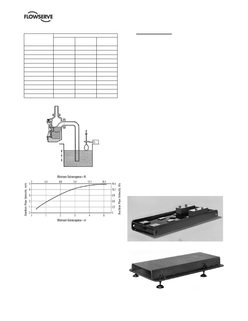
Figure 3-11: Minimum submergence
Figure 3-12: Minimum submergence
3.4.6
Viscosity limitations
The allowable viscosity range for Guardian G & H
series pumps is 0.25 cP to 300 cP. Please consult
your Flowserve representative for services with
viscosities less than 0.25 cP.
3.4.7
Entrained solids
For process fluids with entrained solids the following
restrictions apply to the solids particles:
•
300 micron (0.012 in.) maximum diameter
•
Less than 3.0 % solids by weight
•
2 Moh hardness or less (roughly equivalent to
gypsum)
•
No ferrous particles
4
INSTALLATION
4.1 Location
The pump should be located to allow room for
access, ventilation, maintenance, and inspection with
ample headroom for lifting and should be as close as
practicable to the supply of liquid to be pumped.
Refer to the general arrangement drawing for the
pump set.
4.2 Part assemblies
The supply of motors and baseplates are optional.
As a result, it is the responsibility of the installer to
ensure that the motor is assembled to the pump and
aligned as detailed in section 4.5 and 4.8.
4.3 Foundation
Protection of openings and threads
When the pump is shipped, all threads and all
openings are covered. This protection/covering
should not be removed until installation. If, for any
reason, the pump is removed from service, this
protection should be reinstalled.
4.3.1
Rigid baseplates - overview
The function of a baseplate is to provide a rigid
foundation under a pump and its driver that maintains
alignment between the two. Baseplates may be
generally classified into two types:
•
Foundation-mounted, grouted design (Figure 4-1)
•
Stilt mounted, or free-standing (Figure 4-2)
Figure 4-1: Foundation mounted baseplate
Figure 4-2: Stilt mounted baseplate